Displaying visually correct pointer movements on a multi-monitor display system

a multi-monitor computer system and pointer movement technology, applied in computing, instruments, electric digital data processing, etc., can solve the problems of monitors in multi-monitor computer systems that are frequently dissimilar, monitors in multi-monitor computer systems that are also dissimilar in screen resolution, and the inability to display information across multiple monitors

Active Publication Date: 2009-07-07
MICROSOFT TECH LICENSING LLC
View PDF4 Cites 43 Cited by
  • Summary
  • Abstract
  • Description
  • Claims
  • Application Information

AI Technical Summary

Problems solved by technology

However, as most multi-monitor computer users will readily appreciate, and as shown in FIG. 1A, the monitors in a multi-monitor computer system are frequently dissimilar, both in physical size as well as other aspects described below.
In addition to differences in physical size, monitors in a multi-monitor computer system may also be dissimilar with regard to screen resolution, i.e., the number of pixels that are displayed on the displayable area of a monitor.
While multi-monitor computer systems are generally very desirable, due to the differences between monitors, as well as the physical separation and physical alignment of multiple monitors, numerous problems arise with regard to displaying information across the multiple monitors.
In particular, some of these problems arise with regard to the visual continuity of a pointer as the pointer is moved across monitor boundaries from a source location to a target location.
Conversely, when pointer movements fail to directly correspond to mouse movements, target acquisition is impeded.
Unfortunately, on multi-monitor computer systems, the visual / spatial correlation between mouse movements and pointer movements is almost always disrupted when the pointer crosses monitor boundaries.
However, on current multi-monitor computer systems, due to any number of conditions, including, but not limited to, the physical separation of monitors 104 and 106, the physical alignment of the monitors, the internal arrangement of the display surface, the screen resolution of the monitors, and the display resolution of the monitors, the user's expectations are not met.
Clearly, this visual discontinuity is extremely disruptive to target acquisition.
Hence a discontinuity in the pointer trajectory as it crosses a boundary between monitors is disruptive to human performance, and is very difficult for a user to compensate for.
However, they do not necessarily reflect the physical arrangement of the corresponding monitors, as a user is free to rearrange the monitors without informing the system 100.
Being contiguous, the display areas clearly cannot account for the physical separation between them, nor do they necessarily account for the actual physical alignment of the monitors.
In addition to physical conditions that exist between monitors, while some current multi-monitor computer systems are aware of the screen resolutions of its monitors, current multi-monitor computer systems are unaware of the pixel resolutions of those monitors.
Unfortunately, as discussed above, monitors frequently differ in pixel resolution and pixel resolution can have a substantial impact on the visual appearance of displayed information, including a pointer 112.
While the calibration information may be determined and advantageously used by software applications, unfortunately, in current multi-monitor computer systems, the pointer 112 can not.
Thus, even when software applications compensate for display differences between monitors, the visual display of the pointer 112 is tied to the computer system's display surface, and is therefore unable to take advantage of the determined calibration information.

Method used


Image

  • Displaying visually correct pointer movements on a multi-monitor display system
  • Displaying visually correct pointer movements on a multi-monitor display system
  • Displaying visually correct pointer movements on a multi-monitor display system

Examples


Embodiment Construction

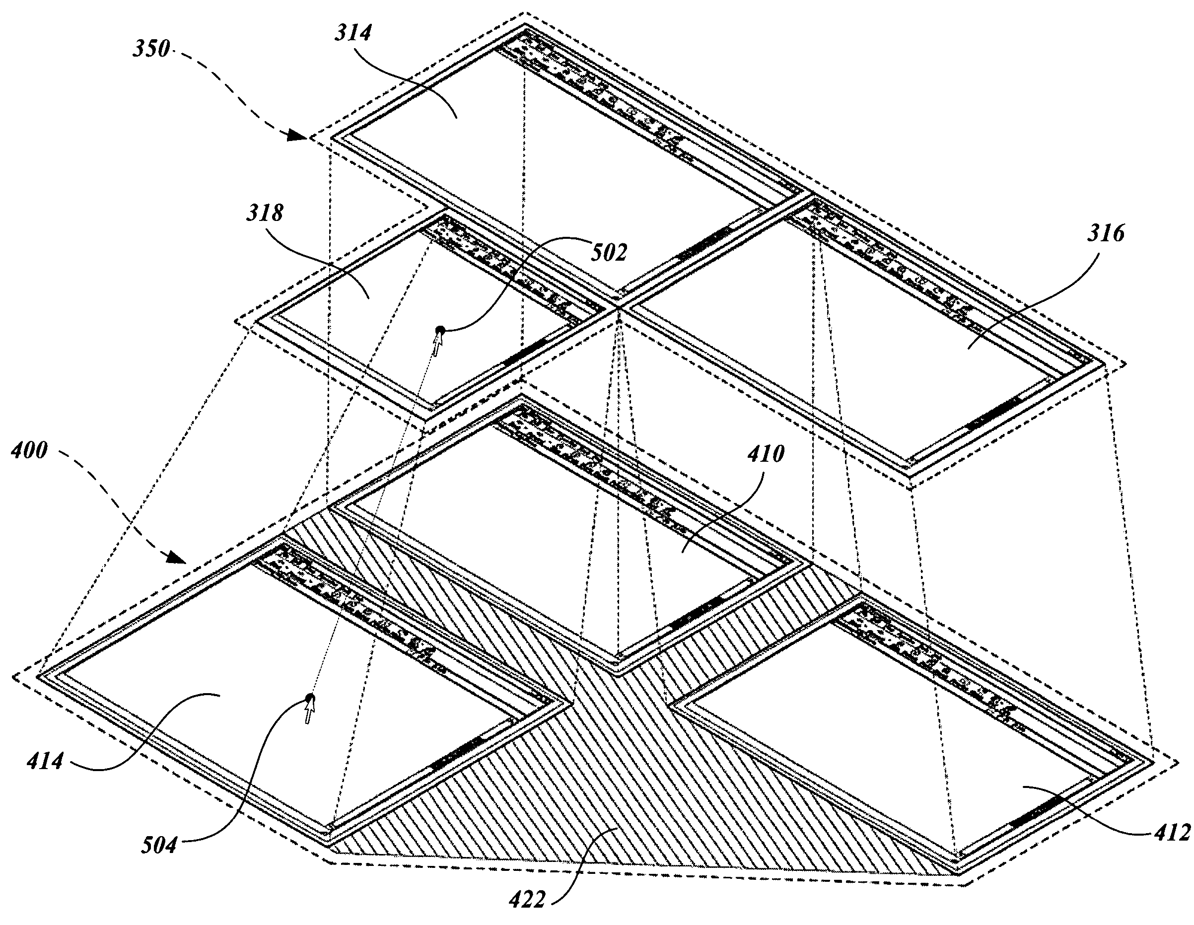
[0043]In order to enable a multi-monitor computer system to display visually correct pointer movements as the pointer crosses monitor boundaries, a virtual space is created. FIG. 4 is a block diagram illustrating exemplary virtual space 400 for the multi-monitor computer system 300 of FIG. 3A. As its name suggests, the virtual space is a conceptual space that corresponds to the physical arrangement and alignment of monitors in the multi-monitor computer system, as well as differences in screen resolutions, pixel resolutions, and the like as determined in the calibration processes, i.e., determining the relative differences among the monitors, described in the incorporated reference.

[0044]While there are some similarities between the internal display surface 350 and virtual space, there are also many differences. For example, a computer system's internal display surface, such as display surface 350 for computer system 300, includes display areas for each monitor. The virtual space 40...


PUM


Abstract

A virtual space for displaying the pointer in a visually correct manner on a multi-monitor computer system is presented. The virtual space is kept separate from the internal display surface of the multi-monitor computer system upon which information is written to be displayed on the monitors. The virtual space is established such that the virtual display areas of the virtual space reflect the visual arrangement of the monitors. The virtual space captures all pointer movements, such as by a mouse or other input device, and moves the pointer within the virtual space. On a pointer update frame, the pointer is mapped from the virtual space to the internal display space such that the pointer may be displayed on the monitors.

Description

FIELD OF THE INVENTION[0001]The present invention relates to displaying pointer movements on a computer system, and more particularly, displaying visually correct pointer movements on a multi-monitor computer system.BACKGROUND OF THE INVENTION[0002]Multi-monitor computer systems, i.e., a computer system with more than one display / monitor, are becoming more and more prevalent. Their prevalence is due, at least in large part, to the fact that (1) the typical graphic display subsystem provides support for more than one monitor and (2) the cost for a second monitor is relatively small. Another factor is that a multi-monitor computer system offers a computer user more area upon which information and work may be displayed. With a greater display area, the computer user spends less time cycling through overlapping windows, frequently referred to as “thrashing,” to find information that may lie hidden under the overlapping windows.[0003]FIG. 1A is a pictorial diagram illustrating an exempla...

Claims


Application Information

Patent Timeline
Patent Type & Authority Patents(United States)
IPC IPC(8): G09G5/00G09G5/08
CPCG06F3/038G06F3/1446G09G2340/0407G09G2320/0693G09G2300/026
Inventor BAUDISCH, PATRICK M.CUTRELL, EDWARD B.HINCKLEY, KENNETH P.GRUEN, ROBERT W.
Owner MICROSOFT TECH LICENSING LLC
Why Eureka
Try Eureka