Tire pressure gauge with displacement limiting members

a technology of displacement limiter and tire pressure gauge, which is applied in vehicle tyre testing, instruments, roads, etc., can solve the problems of tire pressure gauge housing subject to deviation from the original position, affecting not only the airtight effect, and tire pressure gauge failing to accurately detect the tire pressur

Inactive Publication Date: 2009-07-21
MOBILETRON ELECTRONICS
View PDF17 Cites 11 Cited by
  • Summary
  • Abstract
  • Description
  • Claims
  • Application Information

AI Technical Summary

Benefits of technology

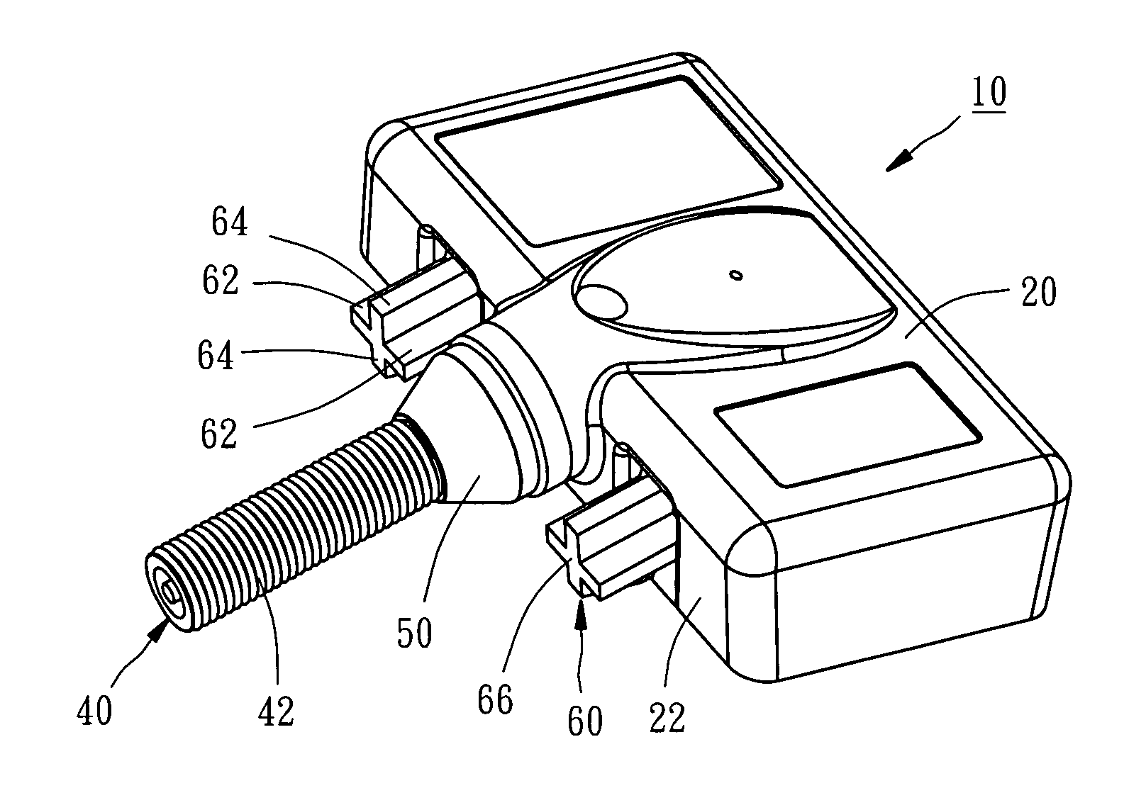
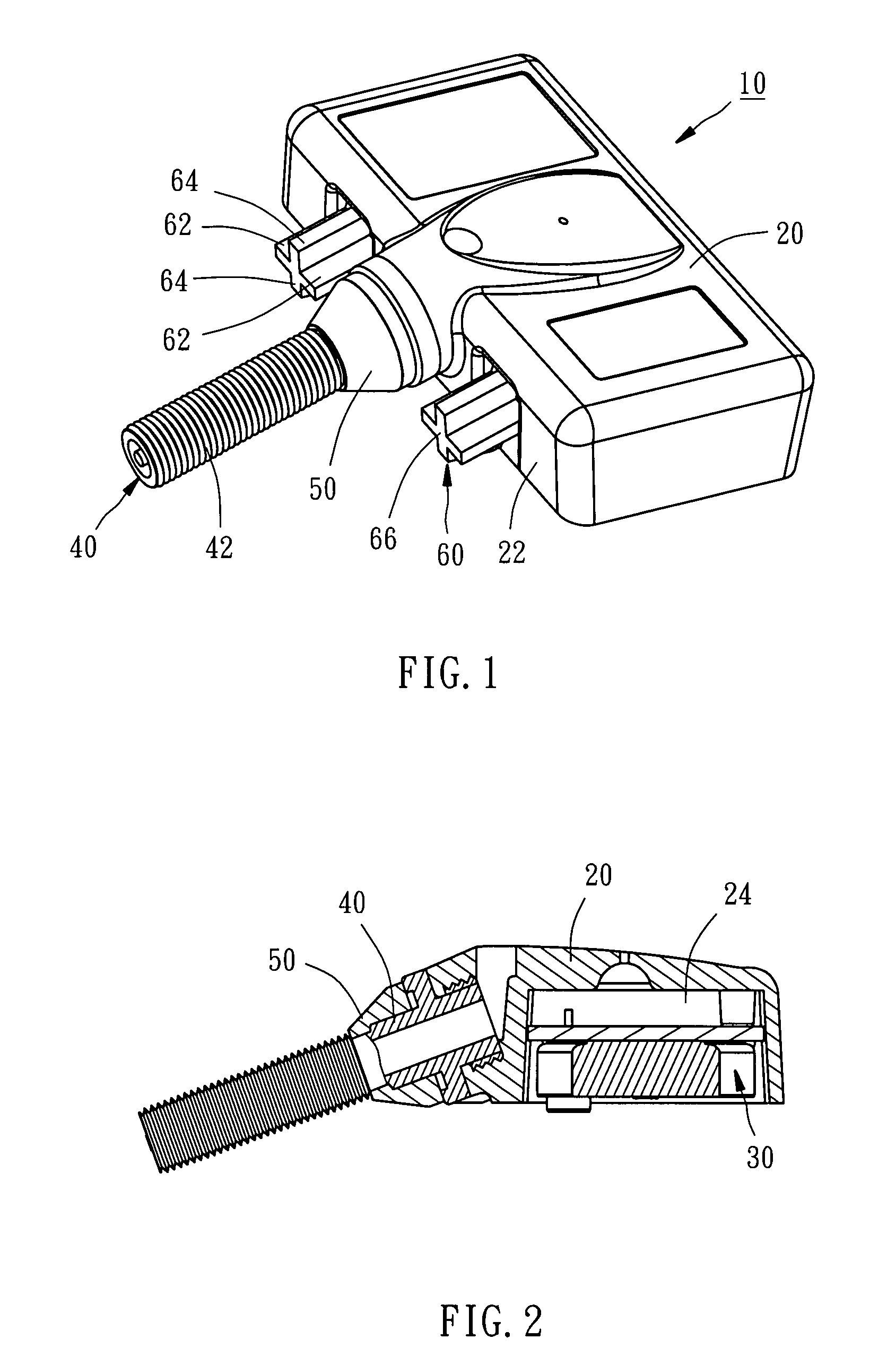
[0006]The primary objective of the present invention is to provide a tire pressure gauge, which can be well positioned to remain in original position while a tire that the tire pressure gauge is applied is violently shocked or impacted.

Problems solved by technology

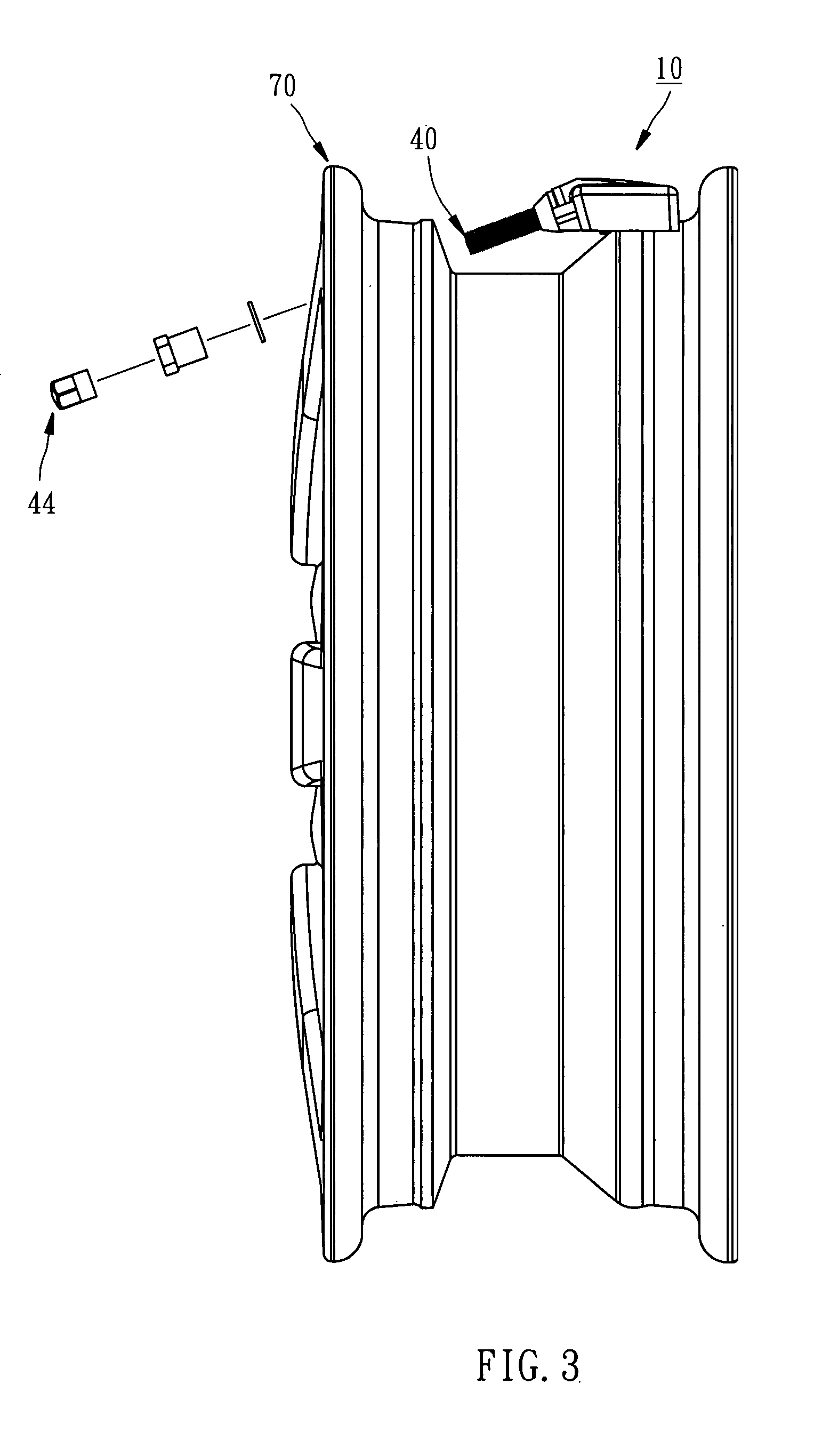
However, the conventional gauge is fixed to the rim by only one screw nut and the housing of the gauge is suspended without any circumferential support.
For this reason, when the car passes though the rough roadbed to cause violent shock of the rim or through the potholes on the roadbed to suffer sudden impact, the housing of the tire pressure gauge is subject to deviation from the original position, affecting not only the airtight efficacy between the sealant and the air valve but also the detecting efficacy of the eccentric switch.
Under the circumstances, the tire pressure gauge fails to accurately detect the tire pressure.

Method used


Image

  • Tire pressure gauge with displacement limiting members
  • Tire pressure gauge with displacement limiting members
  • Tire pressure gauge with displacement limiting members

Examples


first embodiment

[0022]Referring to FIG. 5, a tire pressure gauge 80 constructed according to a second preferred embodiment of the present invention is structurally similar to the first embodiment and different as recited below.

second embodiment

[0023]Each of the limit members 82 of the second embodiment includes a base part 84 and a limit cover 86 made of rubber. The base parts are formed in one piece on the front side 882 of the housing 88. The limit covers 86 each have an end surface 862 and are fitted onto the respective base parts 84 to enable the total length of the base part 84 and the limit cover to be larger than 2 mm. After the limit covers 86 are fitted onto the respective base part 84, the air valve 87 is axially perpendicular to the end surfaces 862 of the limit covers 86 and the end surfaces 862 are parallel to the front side 882 of the housing 88, such that the end surfaces 862 can contact against the rim 70.

[0024]In light of the above structure of the second embodiment, the rubber limit covers contact against the rim to enhance deformation of the limit members for more airtight efficacy between the sealant and the air valve. In addition, the rubber limit covers can increase friction between the limit covers ...


PUM


Abstract

A tire pressure gauge includes a housing, a tire pressure detection unit, an air valve, and at least two limit members. The housing has a lateral side and a chamber. The tire pressure detection unit is mounted in the chamber. The air valve is mounted to the housing, extending out of the chamber from the lateral side of the housing. The at least two limit members are mounted to the lateral side of the housing and located bilaterally at the air valve, each having an end surface to which the air valve is perpendicular. Accordingly, when the tire passes through the rough roadbed to be violently shocked or impacted, the tire pressure gauge of the present invention remains in original position because of positioning efficacy of the two limit members.

Description

BACKGROUND OF THE INVENTION[0001]1. Field of the Invention[0002]The present invention relates generally to a tire pressure gauge, and more particularly, to a well positioned tire pressure gauge.[0003]2. Description of the Related Art[0004]The conventional tire pressure gauge includes a housing, a control circuit board mounted inside the housing, and an eccentric switch electrically connected the control circuit board. An air valve is connected to a front side of the housing and is inserted into a valve receiving hole of the rim, having a threaded portion for threaded connection with a screw nut for further fixture to a rim. A sealant is fitted to the air valve and stopped against the sidewall of the valve receiving hole for superior airtight efficacy. When a car starts to run and then keeps running, the eccentric switch of the tire pressure gauge is activated by the rotation of the rim for detection of the tire pressure.[0005]However, the conventional gauge is fixed to the rim by on...

Claims


Application Information

Patent Timeline
Patent Type & Authority Patents(United States)
IPC IPC(8): G01M17/02
CPCB60C23/0494B60C23/0408
Inventor LIAO, MING-KUAN
Owner MOBILETRON ELECTRONICS
Why Eureka
Try Eureka