Method of making fluid dynamic bearing
a technology of fluid dynamic bearing and bearing body, which is applied in the direction of sliding contact bearings, mechanical equipment, other domestic articles, etc., can solve the problems of unaddressed industry needs and difficult groove manufacturing, and achieve the effect of improving the quality of the bearing
- Summary
- Abstract
- Description
- Claims
- Application Information
AI Technical Summary
Benefits of technology
Problems solved by technology
Method used
Image

Examples
first embodiment
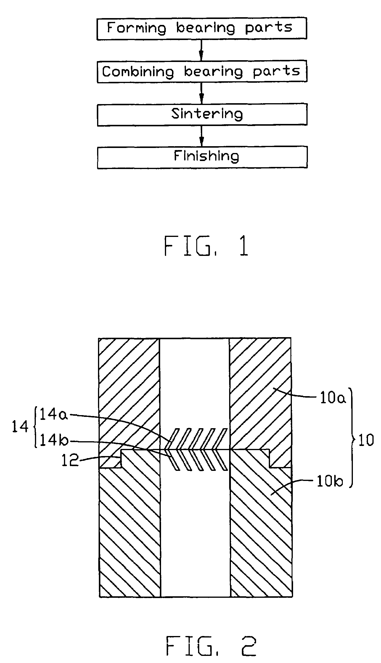
[0025]FIGS. 2-5 illustrate the method of making a fluid dynamic bearing in accordance with the present invention. For better understanding of the present invention, combining and sintering steps are described firstly.
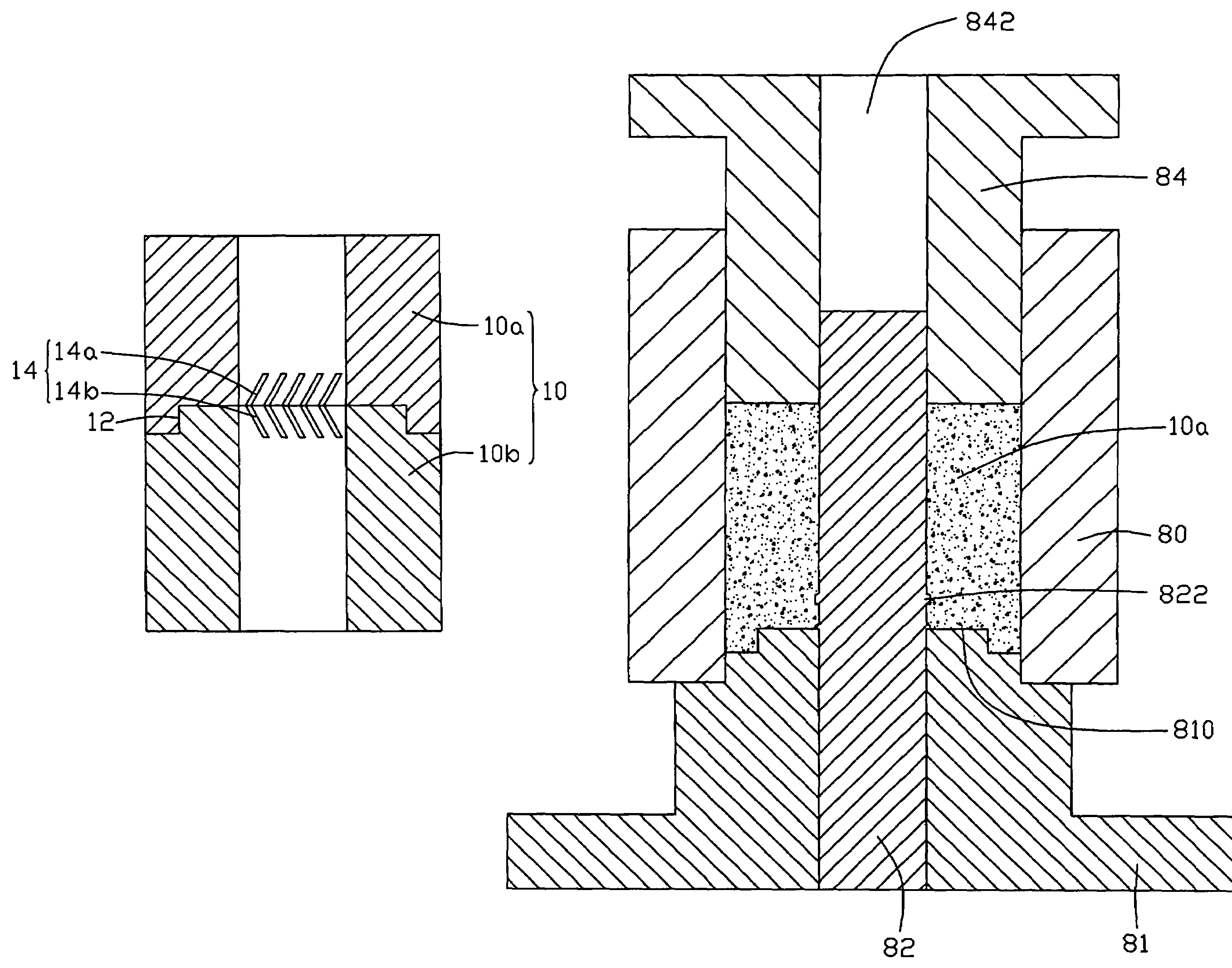
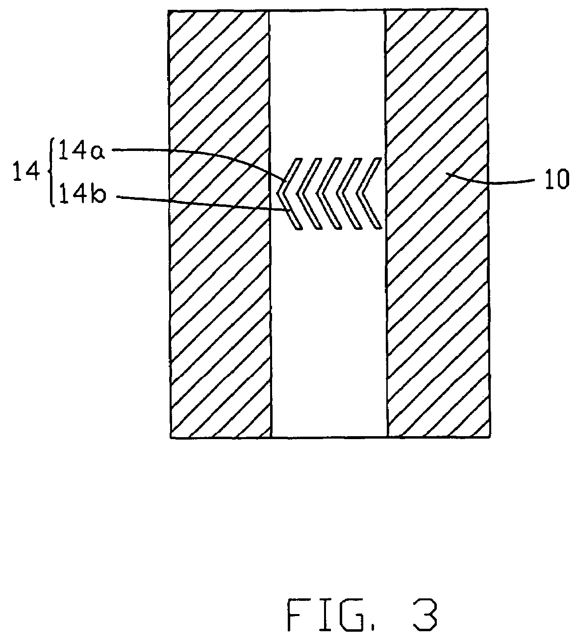
[0026]Referring to FIG. 2, the combining step of the method is depicted. In the first embodiment, a fluid dynamic bearing 10 is comprised of a first bearing part 10a and a second bearing part 10b. The first and second bearing part 10a, 10b are axially joined together in the combining step, to preliminarily form the profile of the fluid dynamic bearing 10. The first and second bearing parts 10a, 10b have their shapes respectively corresponding to divided portions of the fluid dynamic bearing 10 that are divided axially. Each of the first and second bearing parts 10a, 10b comprises a joint plane 12 at one end thereof. For better alignment of the first and second bearing part 10a, 10b, the joint plane 12 is configured to have a step structure. Adhesive is applied on the jo...
second embodiment
[0034]Referring to FIG. 6, according to the present invention, first, second and third bearing parts 22, 24, 26 are joined and sintered to form a fluid dynamic bearing 20. The first and third bearing parts 22, 26 each have a joint plane at one end thereof, and the second bearing part 24 has two joint planes respectively corresponding to the joint planes of the first and third bearing parts 22, 26. A plurality of first groove branches 25a is formed near the joint plane of the first bearing part 22. A plurality of second groove branches 25b is formed near one joint plane of the second bearing part 24. The first groove branches 25a of the first bearing part 22 and the second groove branches 25b of the second bearing part 24 cooperatively form V-shaped grooves 25. A plurality of first groove branches 25a is formed near the other joint plane of the second bearing part 24. A plurality of second groove branches 25b is formed near the joint plane of the third bearing part 24. The first groo...
third embodiment
[0037]Referring to FIGS. 8 and 9, according to the present invention, a first bearing part 30a and a second bearing part 30b are combined and sintered to form a fluid dynamic bearing 30. The first and second bearing parts 30a, 30b have their shapes respectively corresponding to divided portions of the fluid dynamic bearing 30 that are divided generally through a diameter of the fluid dynamic bearing 30 along an axial direction thereof. Each of the first and second bearing parts 30a, 30b forms two joint planes 32 at two sides in a radial direction thereof. Each joint plane 32 has a step structure. The first and second bearing parts 30a, 30b are joined together at the joint planes 32. The fluid dynamic bearing 30 to be formed has a plurality of V-shaped grooves 34. Each groove 34 comprises a first groove branch 34a and a second groove branch 34b that are angled to each other. Each of the first and second bearing parts 30a, 30b forms a part of the first groove branches 34a and a part o...
PUM
| Property | Measurement | Unit |
|---|---|---|
| height | aaaaa | aaaaa |
| dynamic pressure | aaaaa | aaaaa |
| step structure | aaaaa | aaaaa |
Abstract
Description
Claims
Application Information