Flag management in processors enabled for speculative execution of micro-operation traces

a micro-operation trac and flag management technology, applied in the direction of program control, instruments, computation using denominational number representation, etc., can solve the problems of increased power consumption, increased work expense, and inability to write accurate values

Active Publication Date: 2009-07-28
SUN MICROSYSTEMS INC
View PDF11 Cites 24 Cited by
  • Summary
  • Abstract
  • Description
  • Claims
  • Application Information

AI Technical Summary

Problems solved by technology

The values written may not be correct (yet), as prior micro-operations may not have completed, leaving some outstanding flag updates still to be processed.
In some usage scenarios, the second technique performs less work (and thus consumes less power) than the first technique when there are no atomic trace aborts, at the expense of additional work (and thus greater power consumption) when there is an atomic trace abort.

Method used


Image

  • Flag management in processors enabled for speculative execution of micro-operation traces
  • Flag management in processors enabled for speculative execution of micro-operation traces
  • Flag management in processors enabled for speculative execution of micro-operation traces

Examples


operational examples

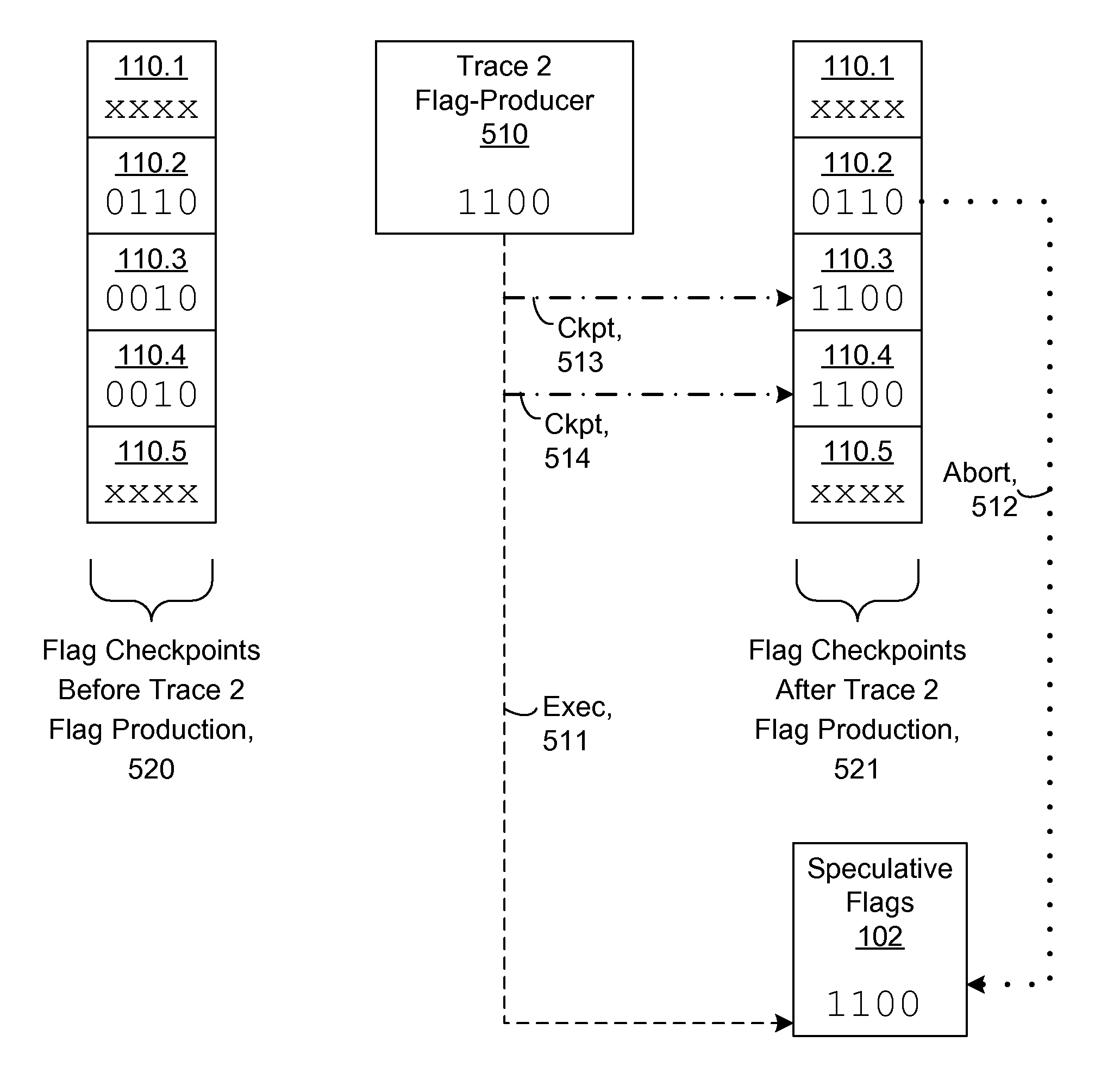
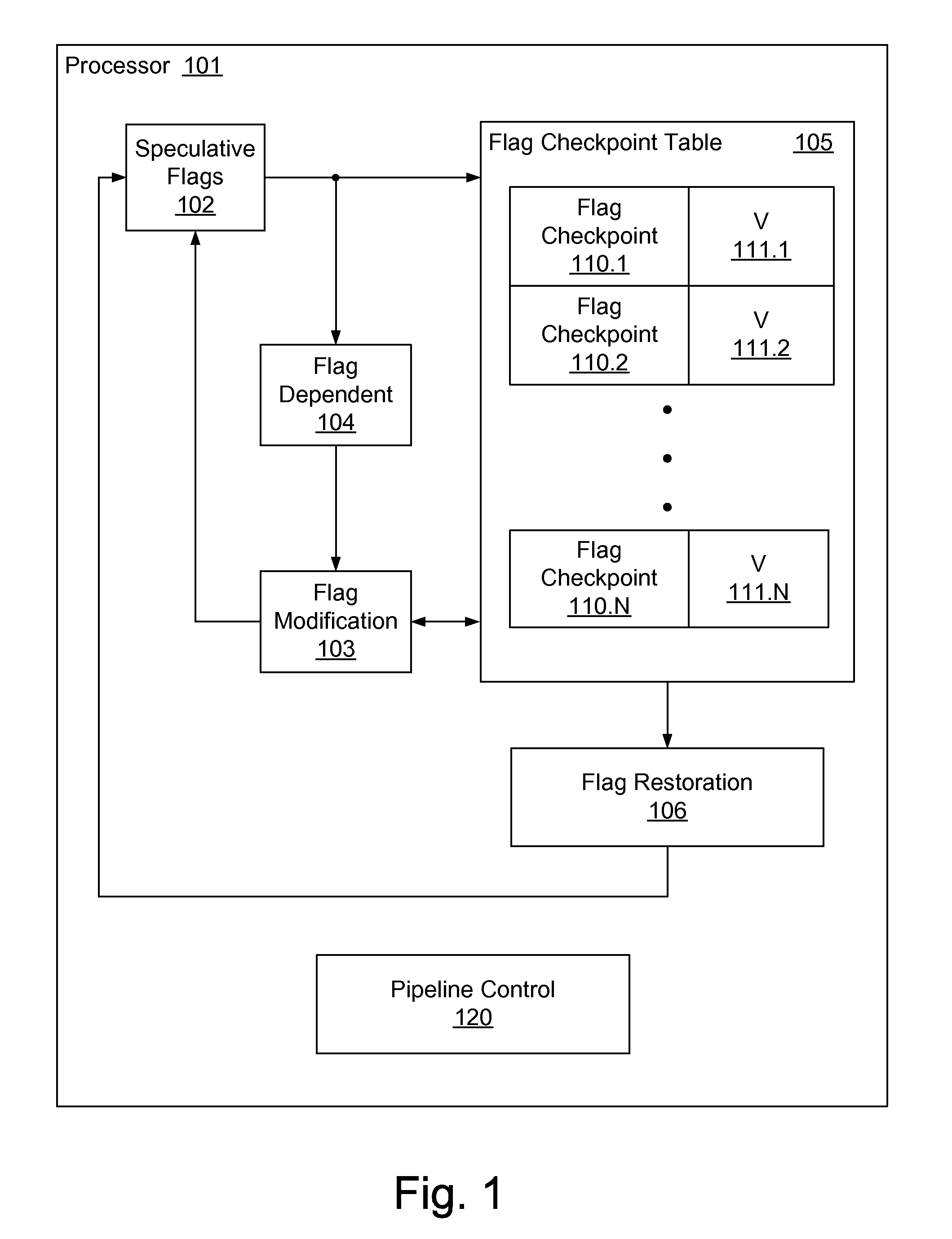
[0080]FIG. 5 illustrates an example of operation of an embodiment according to the first technique for checkpoint / restore of flags with respect to atomic traces. “Flag Checkpoints Before Trace 2 Flag Production”520 illustrates exemplary information retained in various Flag Checkpoints 110.1-110.5 (as embodied in Flag Checkpoint Table 105 of FIG. 1) before changes to the flags have been produced by processing relating to “Trace 2 Flag-Producer”510. “Flag Checkpoints After Trace 2 Flag Production”521 illustrates exemplary information retained in Flag Checkpoints 110.1-110.5 after changes to the flags have been produced by processing relating to “Trace 2 Flag-Producer”510.

[0081]More specifically, before processing relating to “Trace 2 Flag-Producer”510, the flag checkpoints corresponding to Traces 1-5 (Flag Checkpoints 110.1-110.5, respectively) contain values ‘xxxx’, ‘0110’, ‘0010’, ‘0010’, and ‘xxxx’, respectively. Note that each flag checkpoint in the illustrated example operation i...


PUM


Abstract

Managing speculative execution via groups of actions corresponding to atomic traces enables efficient processing of flag-related actions, as atomic traces advantageously enable single checkpoints of flags at trace boundaries. Flag restoration from checkpoints for trace aborts uses a flag checkpoint table to store flag checkpoints, each corresponding to an atomic trace. The table is accessed for flag restoration in response to a trace abort. In a first technique, a corresponding flag checkpoint is stored in response to trace renaming, and the flag checkpoints are updated as flags are modified. Flags are restored from the flag checkpoint corresponding to an aborted atomic trace. In a second technique, a corresponding flag checkpoint is allocated to an invalid state in response to trace renaming, and initialized on-demand when flags are first modified in accordance with the atomic trace. Flags are restored from the oldest flag checkpoint starting from an aborted atomic trace.

Description

CROSS REFERENCE TO RELATED APPLICATIONS[0001]Priority benefit claims for this application are made in the accompanying Application Data Sheet (if any). To the extent permitted by the type of the instant application, this application incorporates by reference for all purposes the following application(s), which are all owned by the owner of the instant application:[0002]U.S. Provisional Application Ser. No. 60 / 730,550, filed Oct. 26, 2005, first named inventor John Gregory Favor, and entitled CHECKPOINTING STATUS FLAGS FOR ATOMIC TRACES;[0003]U.S. Provisional Application Ser. No. 60 / 730,810, filed Oct. 27, 2005, first named inventor John Gregory Favor, and entitled ALLOCATION AND DEALLOCATION OF SHADOW REGISTERS USED BY ATOMIC TRACES;[0004]U.S. Provisional Application Ser. No. 60 / 731,962, filed Oct. 31, 2005, first named inventor John Gregory Favor, and entitled DETERMINING THE HIGHEST PRIORITY ABORT TRIGGER IN AN ATOMIC TRACE;[0005]U.S. Provisional Application Ser. No. 60 / 732,438, f...

Claims


Application Information

Patent Timeline
Patent Type & Authority Patents(United States)
IPC IPC(8): G06F9/30
CPCG06F9/30094G06F9/3863G06F9/3842G06F9/3808
Inventor FAVOR, JOHN GREGORYSONG, SEUNGYOON PETERNELSON, CHRISTOPHER P.
Owner SUN MICROSYSTEMS INC
Why Eureka
Try Eureka