Card connector and card connector assembly

Inactive Publication Date: 2009-08-04
ADVANCED CONNECTEK INC
View PDF1 Cites 41 Cited by
  • Summary
  • Abstract
  • Description
  • Claims
  • Application Information

AI Technical Summary

Benefits of technology

[0008]The main objective of the invention is to provide a card connector that is mounted on a printed circuit board, has hooks and a tray and prevents the hooks from wearing the tray.

Problems solved by technology

However, the stainless steel hooks (7a) easily wear the slides (931, 941) of the aluminum tray (9a).

Method used


Image

  • Card connector and card connector assembly
  • Card connector and card connector assembly
  • Card connector and card connector assembly

Examples


Embodiment Construction

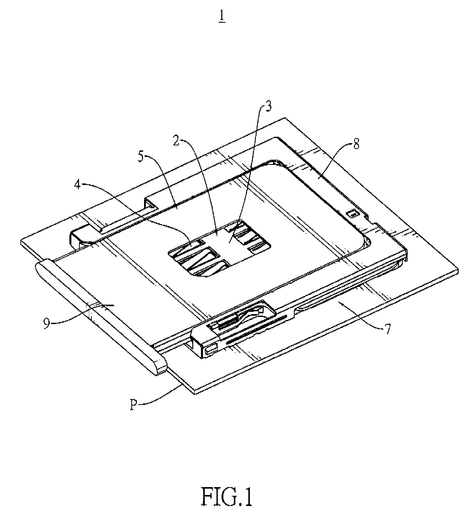
[0020]With reference to FIGS. 1, 2, 3A, 3B and 4, a card connector assembly (5) in accordance with the present invention comprises a printed circuit board (PCB) (P) and a card connector.

[0021]The PCB (P) has a circuit (W) and positioning holes (h).

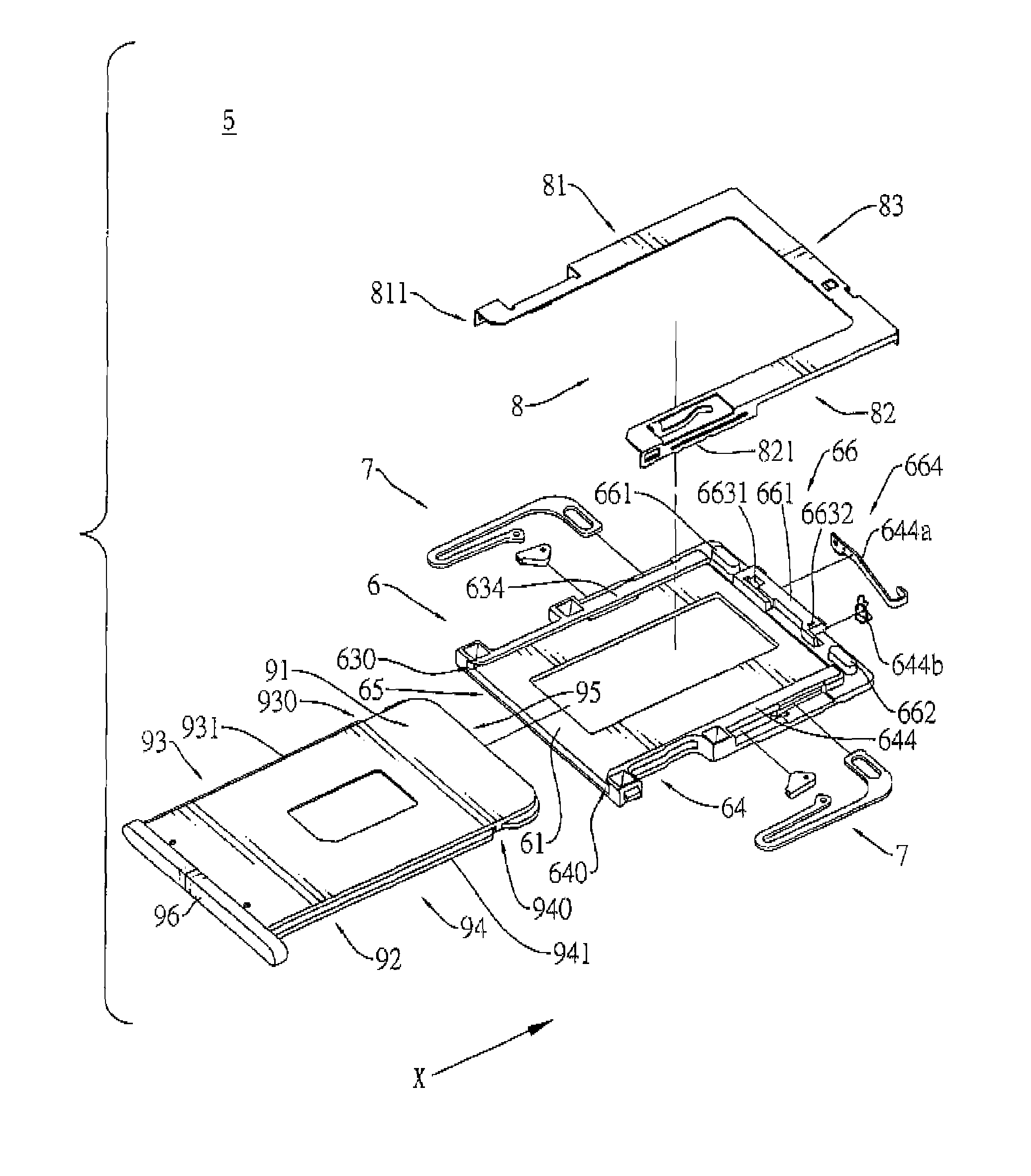
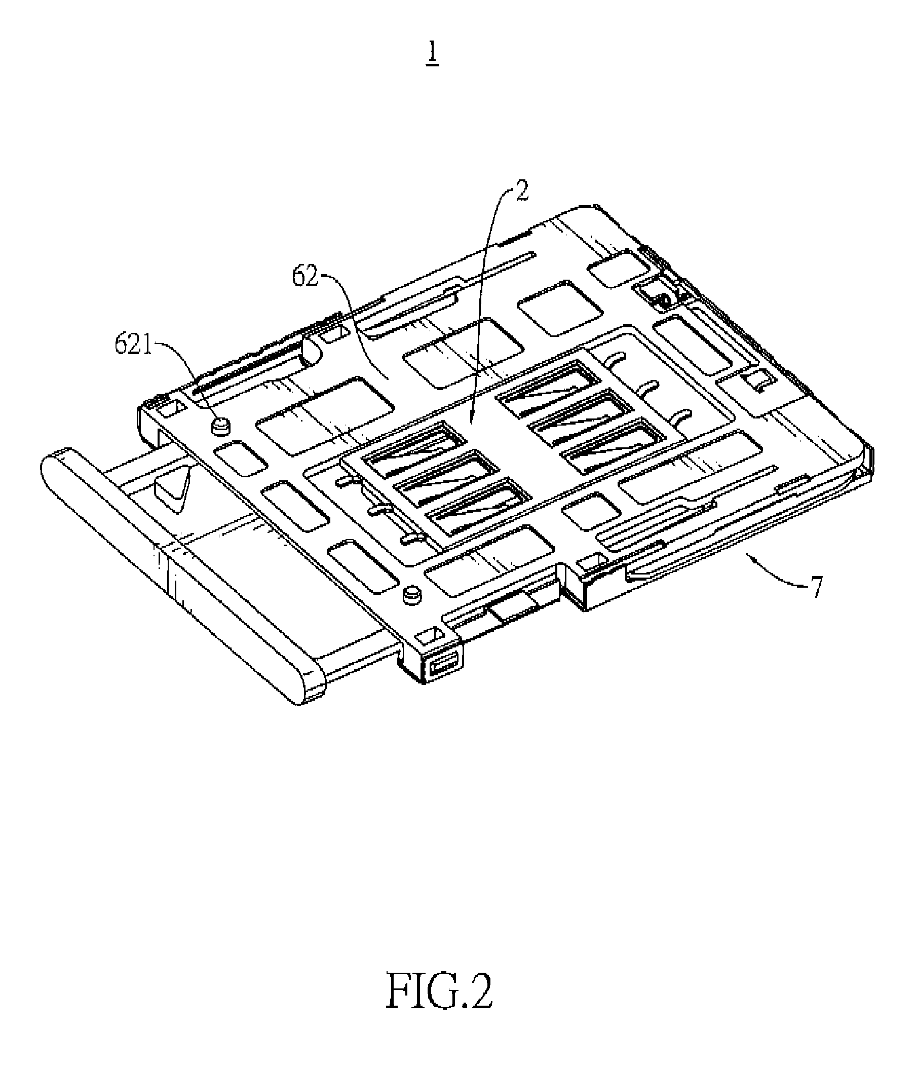
[0022]The card connector is mounted on a printed circuit board (PCB) (P) and may receive a card (S). The card (S) may be a Subscriber Identity Module (SIM) card and has contacts. The arrow (X) in FIG. 3B points to the front of the card connector. The card connector comprises an insulative housing (6), a plurality of terminals (4), a bracket (3), a pair of hook assemblies (7), a cover (8) and a tray (9).

[0023]The insulative housing (6) is rectangular, is mounted on the PCB (P) and has an open top (61), a bottom (62), two opposite sidewalls (63, 64), an open front end (65), a rear end (66), a space, an opening, two rail tabs (634, 644) and two rail slots (630, 640) and may further have two hook mounts (661), a block (663) and a switch.

[0024]...


PUM


Abstract

A card connector is mounted on a PCB and has an insulative housing, a plurality of terminals, a pair of hook assemblies and a tray. The terminals are mounted on the insulative housing. The hook assemblies are mounted on the insulative housing and each hook assembly has a hook and a sheath. The sheath covers the hook. The tray is mounted slidably on the insulative housing and has two slides and two positioning notches defined respectively in the slides and selectively engaged respectively with sheathes on the hooks. The sheathes prevent the hooks from wearing the tray and prevent the slides from deviating.

Description

BACKGROUND OF THE INVENTION[0001]1. Field of the Invention[0002]The present invention relates to a connector, and more particularly to a card connector that is mounted on a printed circuit board, has hooks and a tray and prevents the hooks from wearing the tray.[0003]2. Description of Related Art[0004]With reference to FIG. 7, a conventional card connector (1) is mounted on a printed circuit board (PCB) (P) and has an insulative housing (6a), a plurality of terminals (4a), a bracket (3a), two hooks (7a), a cover (8a) and a tray (9a). The PCB (P) has positioning holes (h) and a circuit (W).[0005]The insulative housing (6a) has two sides and two rail slots (630, 640). The rail slots (630, 640) are longitudinally defined respectively in the sides. The terminals (4a) are mounted in the insulative housing (6a). The bracket (3a) has a plurality of positioning holes to respectively position the terminals in the insulative housing (6a). The hooks (7a) are made of stainless steel and are mou...

Claims


Application Information

Patent Timeline
Patent Type & Authority Patents(United States)
IPC IPC(8): H01R29/00
CPCH01R13/2442H01R13/629H01R13/6275H01R2201/16
Inventor HOU, PIN-YUANWANG, YAO-TEKO, WEN-CHIH
Owner ADVANCED CONNECTEK INC
Why Eureka
Try Eureka