Machine for cutting a planar workpiece and method for pressing out a workpiece part that has been cut free

A technology for processing plates and workpieces, which is applied in the field of machinery and can solve problems such as oblique jamming

Active Publication Date: 2019-03-15
TRUMPF WERKZEUGMASCHINEN GMBH & CO KG
View PDF10 Cites 4 Cited by
  • Summary
  • Abstract
  • Description
  • Claims
  • Application Information

AI Technical Summary

Problems solved by technology

However, in this method, it can happen that the workpiece part that has been cut out (finished part) and the wor...

Method used


Image

  • Machine for cutting a planar workpiece and method for pressing out a workpiece part that has been cut free
  • Machine for cutting a planar workpiece and method for pressing out a workpiece part that has been cut free
  • Machine for cutting a planar workpiece and method for pressing out a workpiece part that has been cut free

Examples


Embodiment Construction

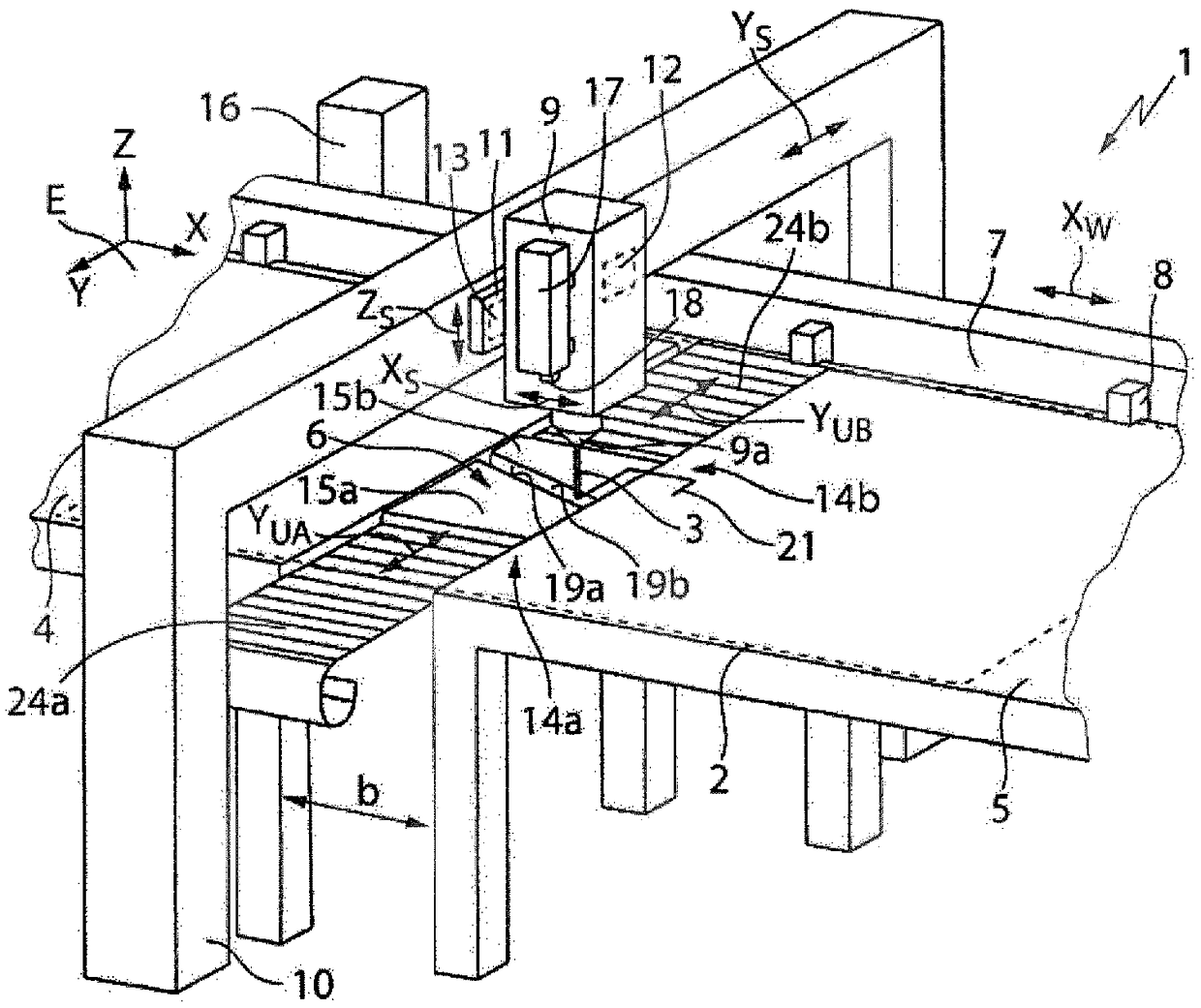
[0054] figure 1 An exemplary structure of a machine 1 for laser processing, more precisely laser cutting, of a plate-shaped workpiece 2 by means of a processing beam in the form of a laser beam 3 is shown. Instead of the laser beam 3 , other types of thermal processing beams, such as plasma torches or water jets, can also be used for cutting the workpiece 2 . Alternatively, the machine 1 can also be designed for the mechanical separation of workpieces 2 , for example as a punching machine or a punching-laser combination machine.

[0055] The workpiece 2 rests during processing on two fixed workpiece mounting surfaces 4, 5 which, in the example shown, form the upper sides of the two workpiece tables and define a The workpiece bearing plane E (X-Y plane of the XYZ coordinate system). The workpiece support surfaces 4, 5 can be formed by workbenches or by pin-shaped support elements (pins), support belts, brushes, rollers, balls, air cushions and the like.

[0056] By means of ...


PUM


Abstract

The invention relates to a machine (1) for cutting a planar workpiece (2), comprising: a first moving device (7) for moving the workpiece (2) in a first direction (X), a second moving device (11) formoving a machining head (9) for the cutting in a second direction (Y), and two workpiece-supporting surfaces (4, 5) for supporting the workpiece (2), between which workpiece-supporting surfaces a gap(6) extending in the second direction (Y) is formed. The machine (1) has a press-out device (17) having a press-out element (18), wherein the press-out element (18) can be moved at least in the seconddirection (Y) within the gap (6) in order to press against a workpiece part (20), which was cut free during the cutting of the workpiece (2), at a specified press-out position (AP). The invention further relates to a method for pressing out a workpiece part (20) which, in particular, was cut free on such a machine (1).

Description

technical field [0001] The invention relates to a machine, in particular a laser processing machine, for the separate processing of plate-shaped workpieces, such as sheet metal, in particular by means of a laser beam, said machine having a first movement device for moving the workpiece in a first direction, for A second moving device for moving the processing head for separate processing along a second direction, especially perpendicular to the first direction, and two workpiece receiving surfaces for receiving workpieces, between which a workpiece receiving surface is formed A slot extending in the second direction. The invention also relates to a method for extruding workpiece parts which are cut out, in particular on such a machine, during a separating process. Background technique [0002] Such a machine for the separate processing of plate-shaped workpieces is known from DE 10 2013 226 818 B4. Such machines have a mixed motion guidance, i.e. the workpiece moves in a f...

Claims


Application Information

Patent Timeline
IPC IPC(8): B23K7/00B23K26/08B23K26/38B23K26/70B23K37/02
CPCB23K7/002B23K37/0288B23K26/0869B23K26/38B23K26/702B23K26/083B26D7/18B26D2007/1872B26D7/1818B26D2007/189B23Q7/006Y10T29/5377Y10T29/53739
Inventor M·戴斯P·埃佩林恩J·奥特纳德F·施毛德D·沃尔夫
Owner TRUMPF WERKZEUGMASCHINEN GMBH & CO KG
Why Eureka
Try Eureka