Integrated pump and ceramic valve

a technology of ceramic valves and integrated pumps, which is applied in the direction of positive displacement liquid engines, piston pumps, machines/engines, etc., can solve the problems of contaminating the liquid being pumped, affecting the operation of the pump, so as to prevent the frictional force between the piston and the barrel during the pumping. , the effect of high pressure seal

Active Publication Date: 2006-07-25
IDEX HEALTH & SCI
View PDF9 Cites 13 Cited by
  • Summary
  • Abstract
  • Description
  • Claims
  • Application Information

AI Technical Summary

Benefits of technology

[0005]The present invention provides a pumping apparatus comprising (a) a displacement pump having a liquid displacement element comprises a piston housed within a barrel, a high pressure seal and means for reciprocating the piston within the barrel and (b) a ceramic valve wherein the sealing surfaces of a ceramic rotor and mating ceramic stator are flat. Control apparatus, including a conventional microprocessor is provided to synchronize movement of the valve rotor and the piston position so that liquid in the barrel is delivered to a point of use while the piston is traveling toward the ceramic valve and liquid is supplied to the barrel when the piston is traveling away from the ceramic valve. The moving piston is spaced apart from the inside surface of the barrel so that a frictional force between the piston and the barrel is prevented during pumping. By providing flat ceramic sealing surfaces, in the ceramic valve, useful pressure at which the liquid is pumped can exceed useful pumping pressures with presently available syringe pumps.

Problems solved by technology

Since organic solvents and diluents are sometimes used to form the liquid being pumped such as dimethylsulfoxide (DMSO) or tetrahydrofuran (THF), the valve rotor commonly swells which causes it to deteriorate.
Also, the use of the conically shaped seal limits the pressure at which the liquid is pumped while retaining desired sealing since higher pressures increase the difficulty in rotating the valve rotor.
Operating pressures are also limited due to the use of polymeric materials in the valve such as polytetrafluoroethylene (PTFE) which tend to cold flow at elevated pressures.
While the available syringe pumps have been useful for their intended purpose, they also have disadvantages.
In addition, when utilizing the most commonly used materials comprising a glass barrel and a (PTFE) face seal, undesirable shedding of the PTFE occurs which contaminates the liquid being pumped.
Furthermore, a tight fit between the barrel and face seal results in chattering of the face seal during its movement within the barrel.
This leads to a loss of control of the liquid volume being pumped.
In addition, the average useful life of presently available syringe pumps is only about 10 to about 100,000 cycles.

Method used


Image

  • Integrated pump and ceramic valve
  • Integrated pump and ceramic valve
  • Integrated pump and ceramic valve

Examples


Embodiment Construction

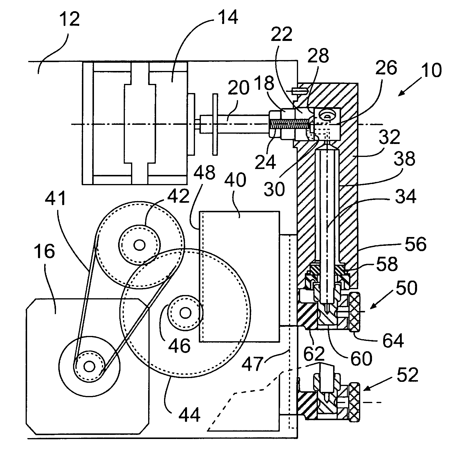
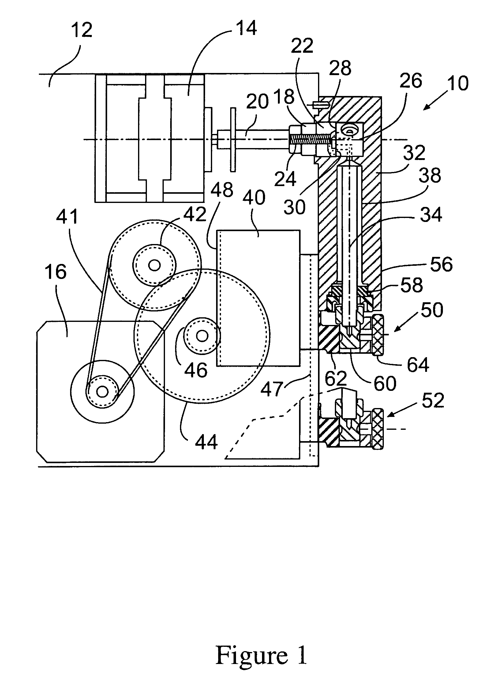
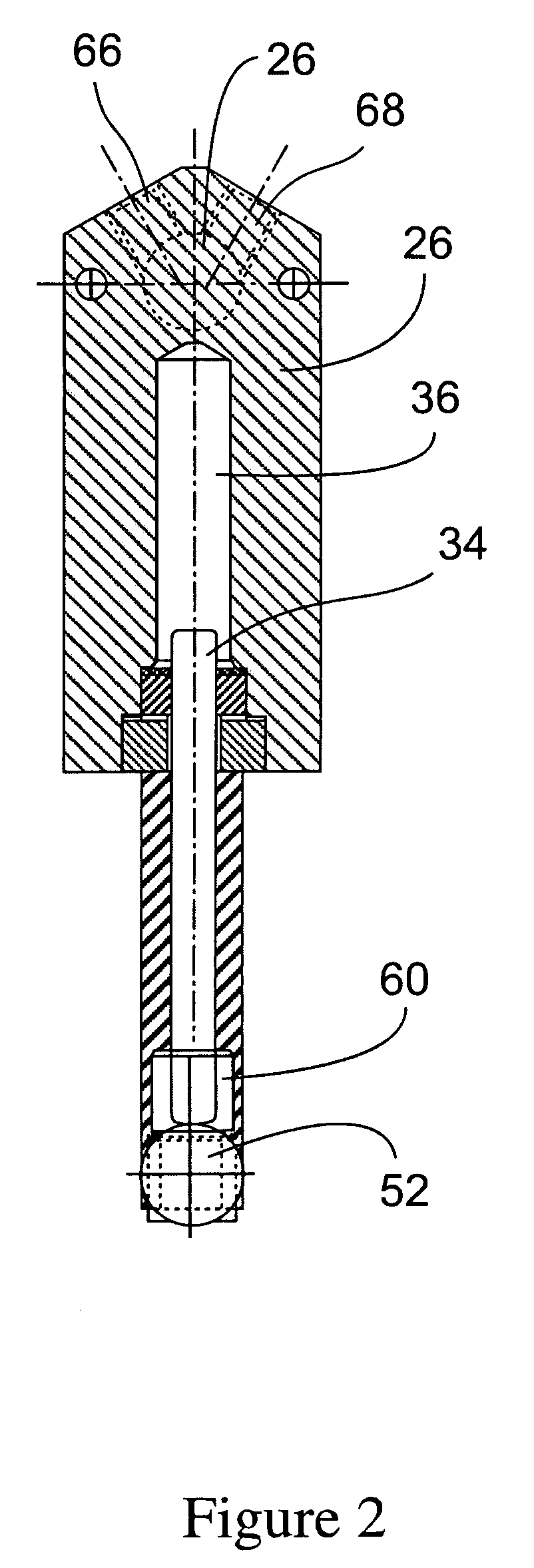
[0016]Referring to FIGS. 1 and 2, the pump apparatus 10 of this invention includes a housing 12 for a motor 14 which effects linear motion such as a stepper motor, a lead screw, a rotary solenoid or the like and a motor 16 which effects rotation. Motor 14 is connected to rotor / stator coupling 18 through arm 20 which can be rigid or a self aligning spring drive. The rotor / stator coupling 18 is biased into ceramic rotor 22 by spring 24. Rotor 22 is sealed against ceramic stator 26 at stator flat polished surface 28 and rotor flat polished surface 30. The ceramic rotor 20 and ceramic stator 26 can be formed of aluminum oxide, zirconia, silica, tantalum oxide, or the like. Mating surfaces 28 and 30 are rendered flat such as by a conventional lapping process. Since mating surfaces 28 and 30 are flat, a significantly lower torque force at a given pressure is required to effect rotation of the rotor as compared to a conically shaped rotor and stator.

[0017]The stator 26 is positioned within...


PUM


Abstract

A pump apparatus is provided which comprises a displacement pump and a ceramic valve construction formed of a ceramic rotor and a ceramic stator having flat surfaces which are positioned in sealing relationship. The displacement pump comprises a reciprocating piston within a housing having an interior wall spaced apart from the piston. The position of the piston and the position of the rotor are controlled to effect desired fluid flow through the stator.

Description

BACKGROUND OF THE INVENTION[0001]This invention relates to an integrated pump and ceramic valve apparatus for pumping discrete liquid volumes to points of use of the liquid volumes. More particularly, this invention relates to an integrated displacement pump and ceramic valve for pumping discrete liquid volumes to points of use.[0002]At the present time, discrete liquid volumes are pumped with a syringe pump comprising a barrel, a face seal which moves within the barrel and a reciprocating plunger attached to the face seal. The syringe pump includes a valve construction formed of a polymeric composition which directs the pumped liquid volumes to a point of use. The valve construction includes a housing having a hollow, essentially conical interior surface into which is press fit a mating, essentially conical rotor. The rotor is provided with fluid passageways that control flow of liquid into the syringe pump and flow of liquid from the syringe pump while providing sealing between a ...

Claims


Application Information

Patent Timeline
Patent Type & Authority Patents(United States)
IPC IPC(8): F04B7/00F04B39/08
CPCF04B7/0007F05C2203/08F04B2205/09Y10T137/86646
Inventor BESSE, KEITHBOHLIN, JONNURNBERG, STEVENSIMONETTI, PAUL
Owner IDEX HEALTH & SCI
Why Eureka
Try Eureka