Dual-motor optical element axial adjustment device

A technology for optical components and adjustment devices, which is applied in the direction of optical components, optics, exposure devices for photolithography, etc., can solve the problems of difficult processing, large number of drivers, complex mechanisms, etc., and achieve low processing costs, compact overall structure, and The effect of a small amount

Inactive Publication Date: 2013-12-25
CHANGCHUN INST OF OPTICS FINE MECHANICS & PHYSICS CHINESE ACAD OF SCI
View PDF6 Cites 11 Cited by
  • Summary
  • Abstract
  • Description
  • Claims
  • Application Information

AI Technical Summary

Problems solved by technology

[0004] In order to solve the problem that there are many drivers in the existing optical element centering device, the mechanism is complicated, and t

Method used


Image

  • Dual-motor optical element axial adjustment device
  • Dual-motor optical element axial adjustment device
  • Dual-motor optical element axial adjustment device

Examples


Embodiment Construction

[0014] The present invention will be described in further detail below in conjunction with the accompanying drawings.

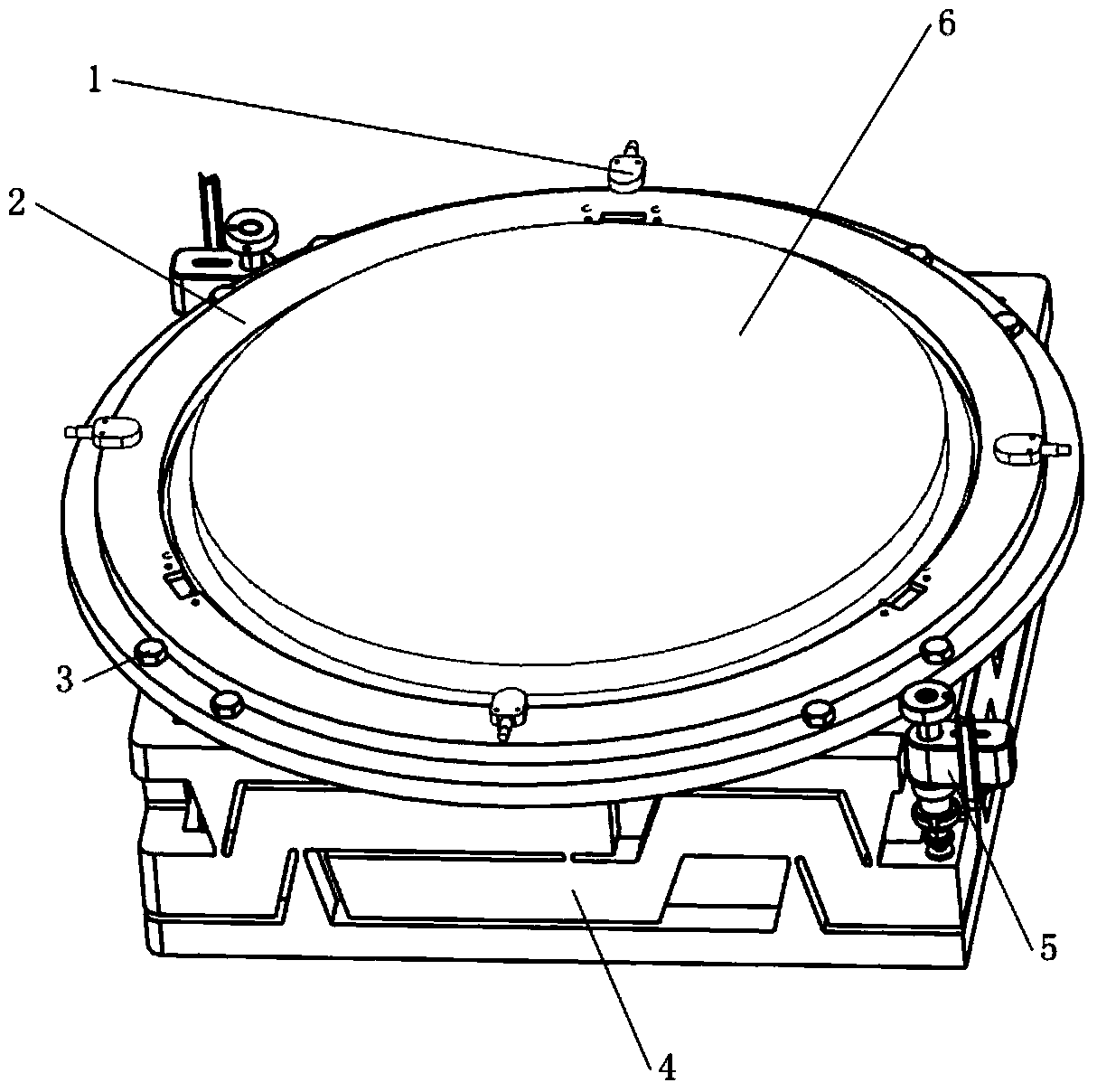
[0015] Such as figure 1 As shown, the dual-motor optical element axial adjustment device includes four capacitive sensors 1 , a mirror frame 2 , eight coupling screws 3 , a compliant drive block 4 and two piezoelectric drivers 5 . The mirror frame 2 and the pliable driving block 4 are fixed by eight coupling screws 3 . The four capacitive sensors 1 are respectively arranged parallel to the upper surface of the mirror frame 2, are evenly distributed along the upper edge of the mirror frame 2, and correspond to the midpoints of each right-angled side of the compliant driving block 4, so as to feedback the magnitude of displacement. Two piezoelectric drivers 5 are respectively arranged at diagonal positions of the compliant driving block 4 . The optical element 6 is fixed in the spectacle frame 2 by bonding after self-alignment.

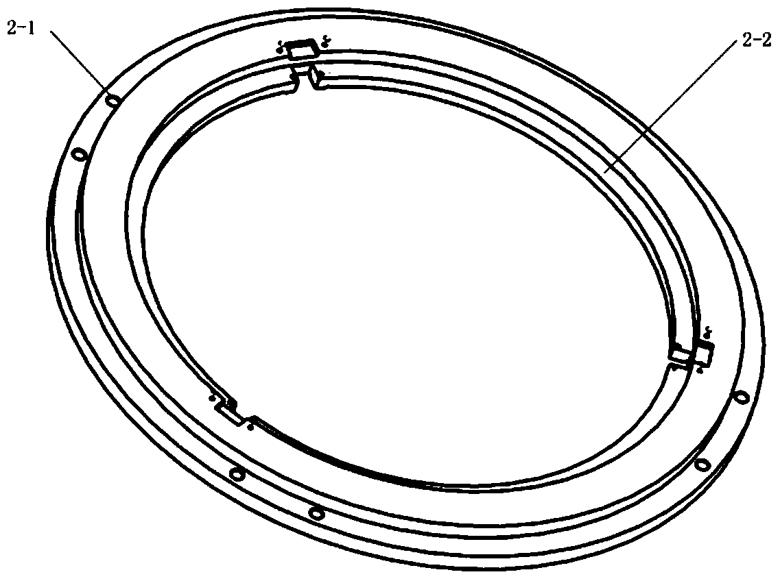
[0016] Such as figure 2 As...


PUM


Abstract

The invention provides a dual-motor optical element axial adjustment device, relates to the technical field of deep ultraviolet projection photoetching objective lens structural design and adjustment, and aims to solve the problems that an existing optical element aligning device is provided with a large number of actuators and is complex in mechanism and high in processing difficulty. The dual-motor optical element axial adjustment device comprises four capacitive sensors, an optical frame, eight connection screws, a smooth driving block and two piezoelectric actuators. The four capacitive sensors are placed parallel to the upper surface of the optical frame, are evenly distributed along the upper edge of the optical frame, and correspond to the midpoints of all right-angle sides of the smooth driving block. The optical frame and the smooth driving block are fixed through the connection screws. The two piezoelectric actuators are arranged at the diagonal positions of the smooth driving block respectively. An optical element is arranged in the optical frame. By means of the dual-motor optical element axial adjustment device, rapid and precise adjustment is realized, and meanwhile, the problems of friction, lubrication and hysteresis of a mechanical hinge are avoided; the smooth driving block acts on the optical frame so that damage to the surface form of the optical element by adjustment force can be effectively lowered; the structure is simple, a small number of motors are needed, and processing cost is low.

Description

technical field [0001] The invention relates to the technical field of structure design and adjustment of deep ultraviolet projection lithography objective lens, in particular to a dual-motor optical element axial adjustment device that can be used in lithography projection objective lens system. Background technique [0002] Projection lithography equipment, as one of the key equipments in the manufacture of large-scale integrated circuits, has become a research hotspot in recent years. With the improvement of the fineness of integrated circuits, the resolution requirements of projection optical equipment are gradually increasing. At present, ArF excimer laser projection lithography equipment with a wavelength of 193.368nm has become the mainstream equipment for 90nm, 65nm and 45nm node integrated circuit manufacturing. During the assembly process of the projection lithography objective lens, various aberrations of the optical system need to be compensated in order to obtai...

Claims


Application Information

Patent Timeline
IPC IPC(8): G02B7/00G03F7/20
Inventor 彭海峰巩岩孙振华洋洋郭抗倪明阳
Owner CHANGCHUN INST OF OPTICS FINE MECHANICS & PHYSICS CHINESE ACAD OF SCI
Why Eureka
Try Eureka