Tripod type constant velocity universal joint

Inactive Publication Date: 2006-02-09
NTN CORP
View PDF3 Cites 14 Cited by
  • Summary
  • Abstract
  • Description
  • Claims
  • Application Information

AI Technical Summary

Benefits of technology

[0018] In the tripod type constant velocity universal joint thus constructed, the second reduced-thickness portion is formed in a groove shape having a rectangular or a curved cross-section. Accordingly, reducing the thickness in the same amount as a conventional structure, wherein a region on an outer periphery of the outer joint member corresponding to the track groove is scraped off to be flat, can increase the circumferential length of a maximum rotation radius portion of the outer joint member. The thickness reduction amount herein referred to means a volume of space enclosed by a cylinder having a radius equal to the maximum rotation radius of the outer joint member and the second reduced-thickness portion. The increase in circumferential length of the maximum rotation radius portion of the outer joint member leads to an increase in inner circumferential length of a maximum inner diameter portio

Problems solved by technology

This incurs an excessive frictional force inside the joint, w

Method used


Image

  • Tripod type constant velocity universal joint
  • Tripod type constant velocity universal joint
  • Tripod type constant velocity universal joint

Examples


first embodiment

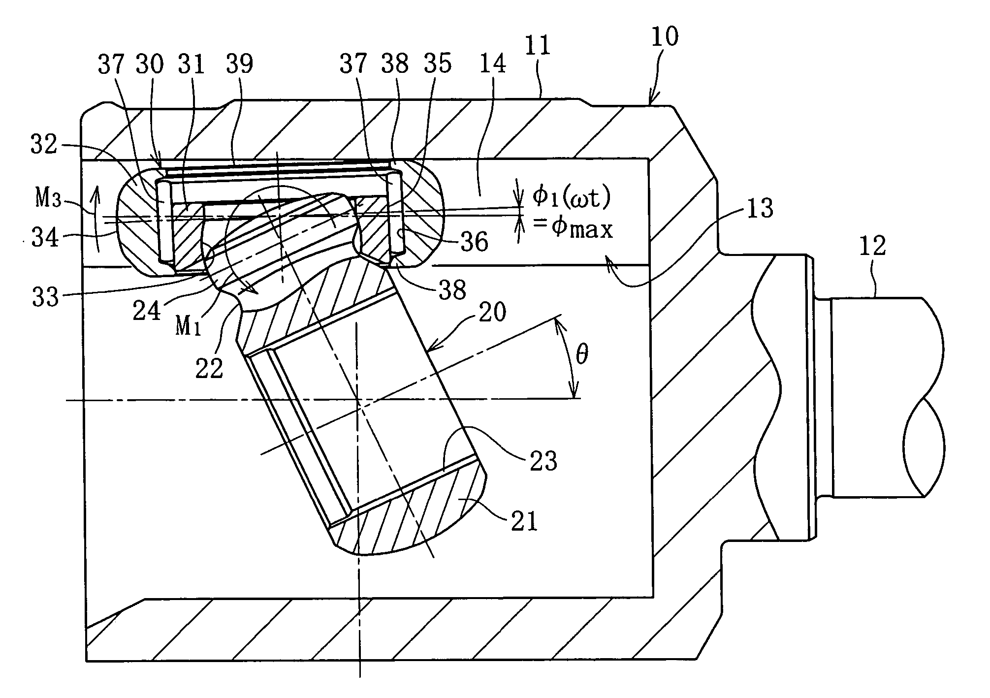
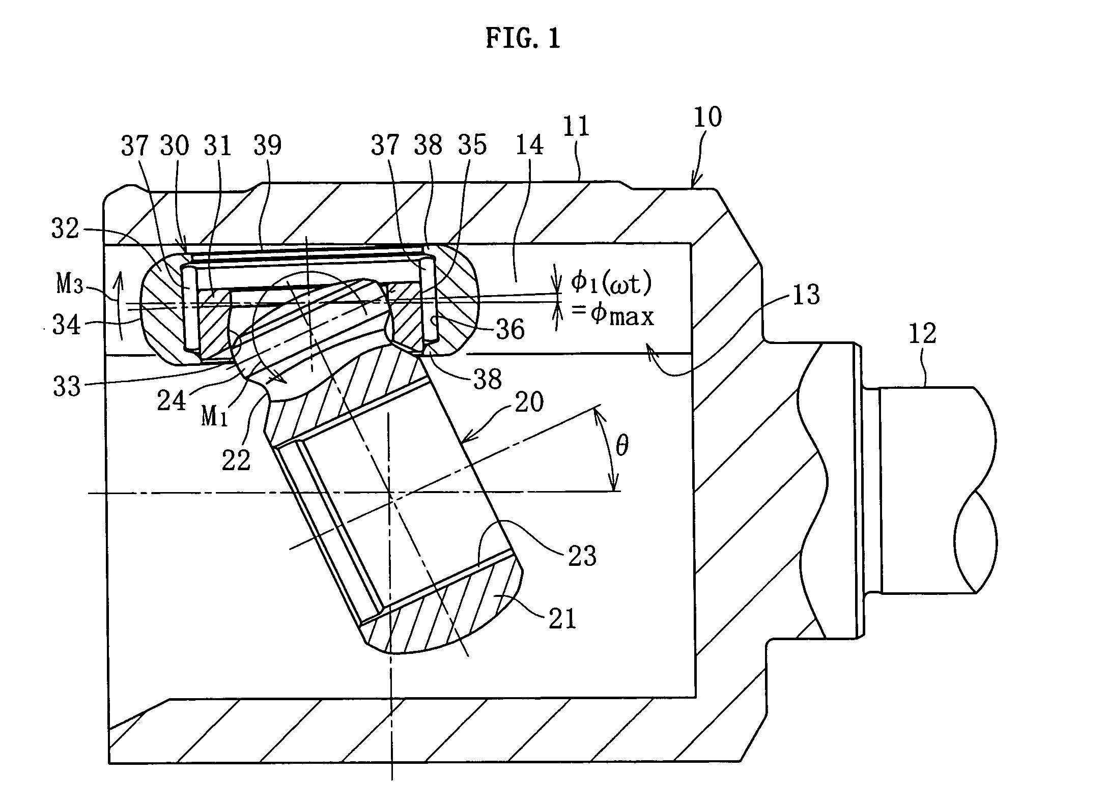
[0046] That is the basic structure of the tripod type constant velocity universal joint in which, as shown in FIG. 2, the track groove bottom portion 15 opposing a facet 39 of the outer roller 32 is formed in a flat surface communicating between outer end portions in a radial direction of the pair of roller guide sections 14, and the track groove bottom portion 15 is located close to the facet 39 of the outer roller, so that the facet 39 of the outer roller, which is inclined when a torque is applied, can contact the track groove bottom portion 15. When a torque is not applied, the track groove bottom portion 15 and the facet 39 of the outer roller define a predetermined clearance therebetween, as shown in FIG. 2.

[0047] The following passage covers an operation of the tripod type constant velocity universal joint according to the first embodiment. Referring to FIG. 1, when a torque is applied with the outer joint member 10 and the inner joint member 20 oriented with an operating an...

third embodiment

[0058] For the tripod type constant velocity universal joint a relation between an annularity A (=r1, / R1) represented by a ratio of the generatrix curvature radius with respect to the outer radius R1 of the outer roller 32 and various inclinations of the outer roller 32 inside the track groove 13 has been focused, so as to determine the clearance δ1 between the outer circumferential surface 34 of the outer roller and the non-load side roller guide section 14, as well as the clearance δ2 between the facet 39 of the outer roller and the track groove bottom portion 15. Specifically, when the annularity A is smaller, the outer roller 32 is inclined by a greater angle in a cross-section perpendicular to an axial line of the outer joint member 10, and the outer circumferential surface 34 of the outer roller and the non-load side roller guide section 14 more readily contact each other, while in a cross-section including an axial line of the outer joint member 10, a restoring couple M3 (Re...

fourth embodiment

[0065] In FIG. 12, the numeral 110 designates an outer joint member, which includes a one-end open cylindrical mouth portion 111 and a stem portion 112 to be connected to one of two shafts to be joined (not shown), so as to transmit a torque. On an inner circumferential surface of the mouth portion 111, three axially extending track grooves 113 are provided on positions equally dividing the circumference into three portions, as shown in FIG. 13. On both sides of the track grooves 113 in a circumferential direction, a pair of roller guide sections 114 is located so as to oppose each other. Each of the roller guide section 114 is a curved recess having a generally arc-shaped cross-section. The track groove bottom portion 115 is formed in a flat surface communicating between outer end portions in a radial direction of the pair of roller guide sections 114. The outer joint member 110 includes a first reduced-thickness portion 116 having a smaller diameter than a maximum rotation diamete...


PUM


Abstract

The invention provides a tripod type constant velocity universal joint that can restrain generation of an excessive frictional force inside the joint because of the rotation phase angle of the inner joint member, thereby suppressing vibration and achieving higher rotation durability. The tripod type constant velocity universal joint includes an outer roller rotatably located inside the roller guide section of the outer joint member, and an inner roller spherically fitted to the trunnion of the inner joint member so as to be pivotally rotatable, and to support the outer roller permitting relative rotation and relative axial movement, so that when a torque is applied with the outer joint member and the inner joint member oriented with an operating angle θ, a facet of the outer roller inclined along with the rotation of the inner joint member is sustained by the track groove bottom portion formed in a flat plane.

Description

BACKGROUND OF THE INVENTION [0001] 1. Field of the Invention [0002] The present invention relates to a tripod type constant velocity universal joint to be incorporated in for example a driving system of an automobile, for transmission of a rotational force mainly between non-linearly oriented rotating shafts. [0003] 2. Description of the Related Art [0004]FIG. 8 is a cross-sectional view showing a conventional tripod type constant velocity universal joint 41, for example disclosed in JP-A No. 2002-147482, including an inner joint member 44 having three trunnions 45 radially projecting from its outer circumferential surface, respectively engaged via a roller assembly 46 in each of three track grooves 43 provided on an inner circumferential surface of an outer joint member 42, so as to transmit a torque between the outer joint member 42 and the inner joint member 44, while allowing angular and axial displacement with respect to each other. [0005] The tripod type constant velocity univ...

Claims


Application Information

Patent Timeline
IPC IPC(8): F16D3/26
CPCF16D3/2055F16D2003/2026F16D3/845Y10S464/905
Inventor IZUMINO, JUNICHIISHIJIMA, MINORU
Owner NTN CORP
Why Eureka
Try Eureka