Golf club head

a golf club head and golf club technology, applied in golf clubs, sport apparatus, golf, etc., can solve the problems of difficulty in controlling the direction in which the ball flies, and the conventional face plate does not sufficiently accommodate the variations in hit points of general amateur golfers, so as to achieve the effect of less carrying

Inactive Publication Date: 2009-08-18
BRIDGESTONE SPORTS
View PDF37 Cites 28 Cited by
  • Summary
  • Abstract
  • Description
  • Claims
  • Application Information

AI Technical Summary

Benefits of technology

[0008]The present invention has been made to solve the above problems, and accordingly an object thereof is to provide a metallic hollow golf club head in which a face plate is designed by giving consideration to the variations in hit points of general amateur golfers, so that the decrease in carry is less even for an off-center hit (hit deviating from the sweet spot).
[0010]According to the present invention, in the golf club head in which the face part of the metallic head body having the hollow part therein is formed with the opening communicating with the hollow part, and the metallic face plate is welded to the opening, the notch part connecting with the opening is formed in a part on the toe side of the crown part and a part on the heel side of the sole part; and the upper end portion of the face plate is extended so as to compensate the notch part in the crown part and is welded to the notch part, and the lower end portion thereof is extended so as to compensate the notch part in the sole part and is welded to the notch part. Therefore, the shape of the face plate covers the distribution of hit points of general amateur golfers, so that even for an off-center hit, the decrease in carry becomes less.

Problems solved by technology

Uneven compression causes distortion of the circular cross-sectional shape, which makes it difficult to control the direction that the ball flies.
The conventional face plate has been developed assuming that a golfer hits a ball at the center of a face plate or the periphery thereof, that is, the sweet spot and therefore the conventional face plate does not sufficiently accommodate variations in hit points of general amateur golfers.

Method used


Image

  • Golf club head
  • Golf club head
  • Golf club head

Examples


Embodiment Construction

[0018]A preferred embodiment of the present invention will now be described with reference to the accompanying drawings.

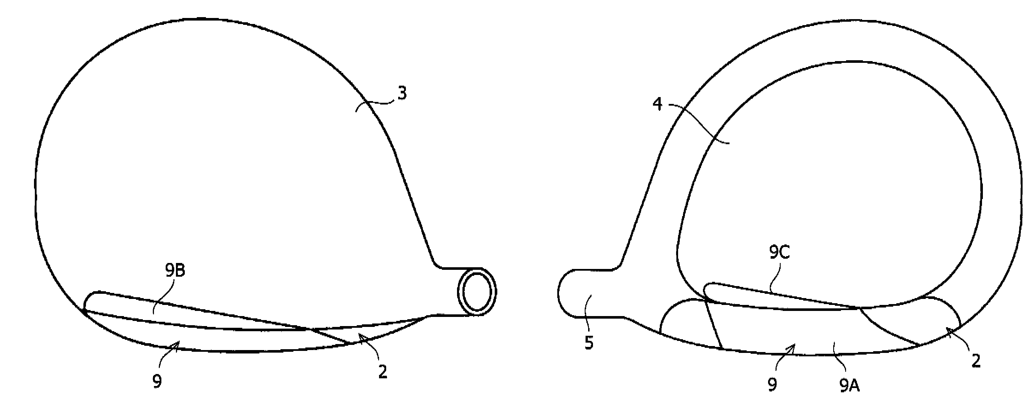
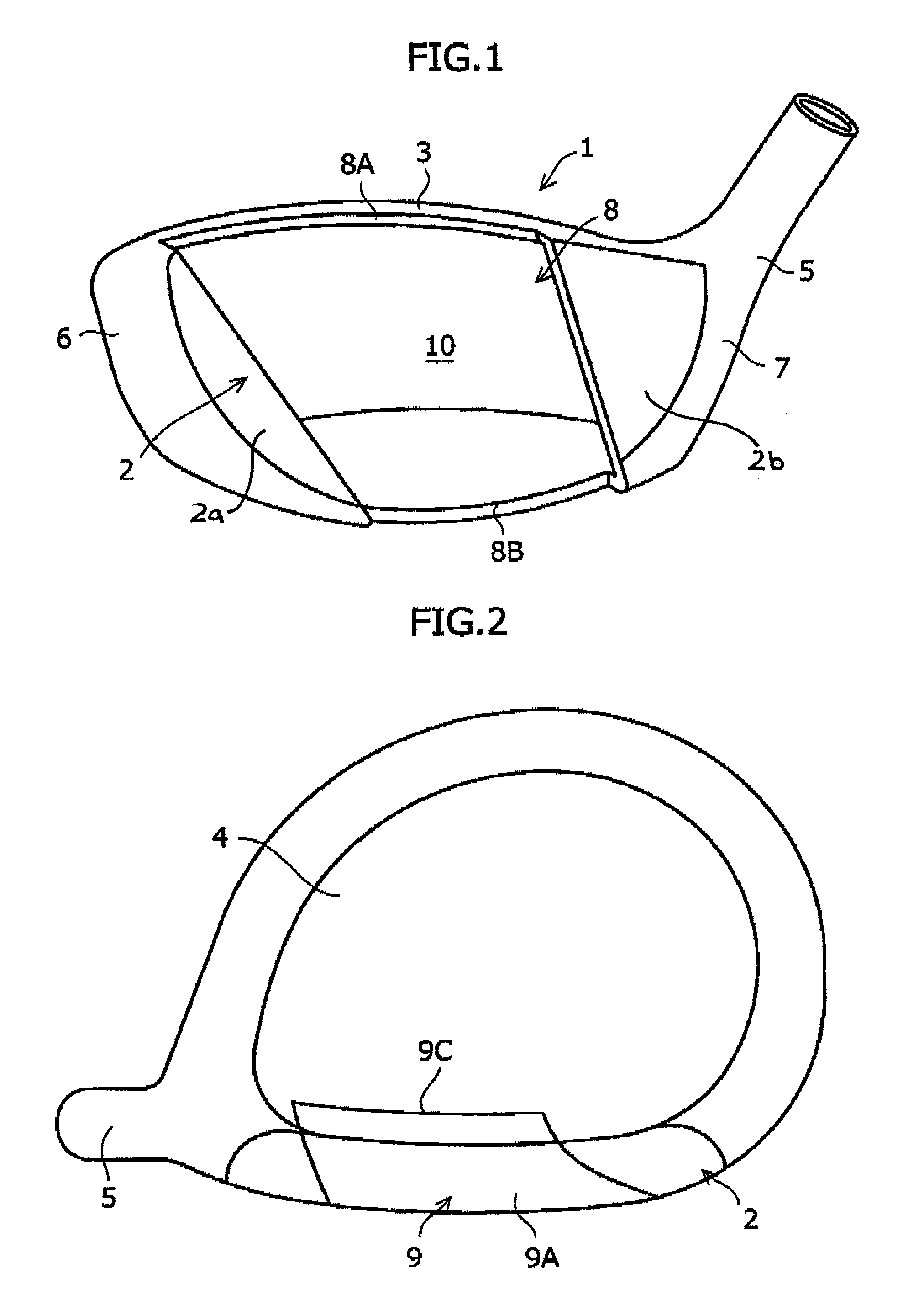
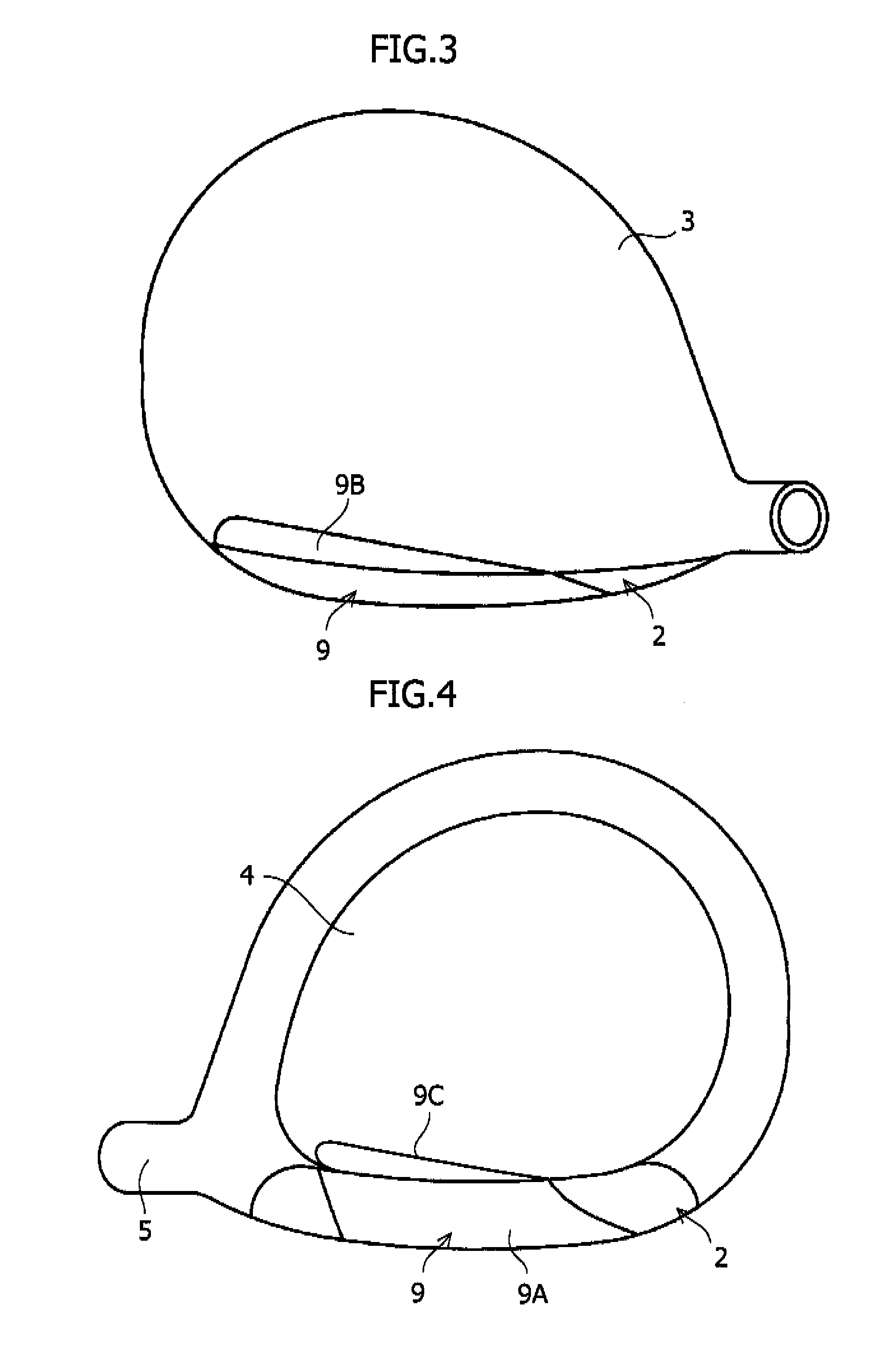
[0019]In FIG. 1, a metallic head body 1 having a hollow part 10 therein is formed with an opening 8 communicating with the hollow part 10. As in the case of the conventional examples the head body 1 includes a face part 2, a crown part 3, a sole part 4, and a hosel 5, and has a toe 6 and a heel 7. Unlike the conventional example, the opening 8 does not have a square shape, but is formed into a rectangular shape such that the front shape tilts to the toe 6 side. Also, a face plate 9 welded to the opening 8 is also formed into a rectangular shape matching the shape of the opening 8.

[0020]The opening 8 is formed between a first part 2a on the toe side of the face part 2 and a second part 2a on the heel side of the face part 2. The opening 8 connects with a notch part 8A formed in a part on the toe 6 side of the crown part 3 and a notch part 8B formed in a part on the ...


PUM


Abstract

The present invention provides a golf club head capable of lessening the decrease in carry even for an off-center hit. In a golf club head in which a face part 2 of a metallic head body 1 having a hollow part therein is formed with an opening 8 communicating with the hollow part, and a metallic face plate 9 is welded to the opening 8, notch parts 8A and 8B connecting with the opening 8 are formed in a part on the toe 6 side of a crown part 3 and a part on the heel 7 side of a sole part 4, respectively; and the upper end portion of the face plate 9 is extended so as to compensate the notch part 8A in the crown part 3 and welded to the notch part 8A, and the lower end portion thereof is extended so as to compensate the notch part 8B in the sole part 4 and welded to the notch part 8B.

Description

BACKGROUND OF THE INVENTION AND RELATED ART STATEMENT[0001]1. Field of the Invention[0002]The present invention relates to a metallic hollow golf club head and, more particularly, to a golf club head in which a face plate is welded to an opening formed in a face part.[0003]2. Description of Related Art[0004]As a conventional metallic hollow golf club head in which a face plate is welded, a golf club head as shown in FIG. 7 has been known. In this golf club head, a substantially rectangular opening 20 is formed in a face part 2 of a metallic head body 1 having a hollow part 10 therein, and a face plate 30 having a shape matching the opening 20 is laser welded to a receiving part 2B formed at the periphery of the opening 20. The head body 1 includes a crown part 3, a sole part 4, and a hosel 5 in addition to the face part 2, and has a toe 6 and a heel 7. In this conventional examples, the welding strength is improved, and therefore damage is less likely to occur (Japanese Unexamined P...

Claims


Application Information

Patent Timeline
Patent Type & Authority Patents(United States)
IPC IPC(8): A63B53/04A63B102/32
CPCA63B53/0466A63B53/047A63B2053/0408A63B2053/0416A63B2053/0462A63B2209/00A63B2053/0458A63B53/0408A63B53/0416A63B53/0458A63B53/0462A63B53/0412A63B53/042A63B2102/32
Inventor MATSUNAGA, HIDEOKUBOTA, MAKOTO
Owner BRIDGESTONE SPORTS
Why Eureka
Try Eureka