

Golf club head
- Summary
- Abstract
- Description
- Claims
- Application Information
AI Technical Summary
Benefits of technology
Problems solved by technology
Method used
Image

Examples
example 1
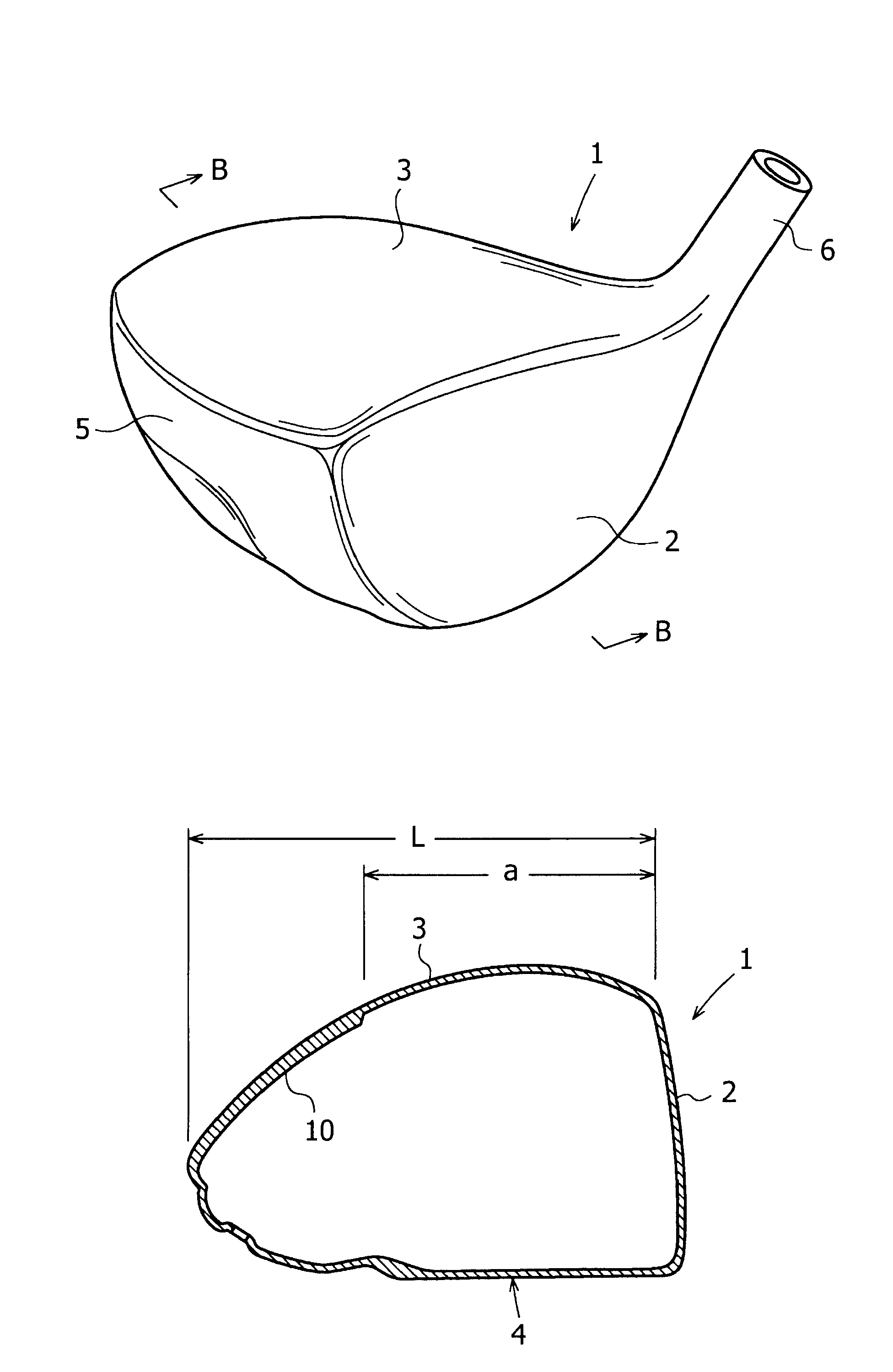
[0044]A golf club head having a volume of 460 cc, which is configured as shown in FIGS. 1 and 2, was manufactured. The head body was formed of (Ti-6Al-4V) α-β type titanium alloy manufactured by the investment casting process. The face plate 30 was manufactured by forging a β type titanium alloy. The modulus of elasticity of this titanium alloy is 110 Gpa.
[0045]The length L is equal to 92 mm, and the width W is equal to 125 mm.
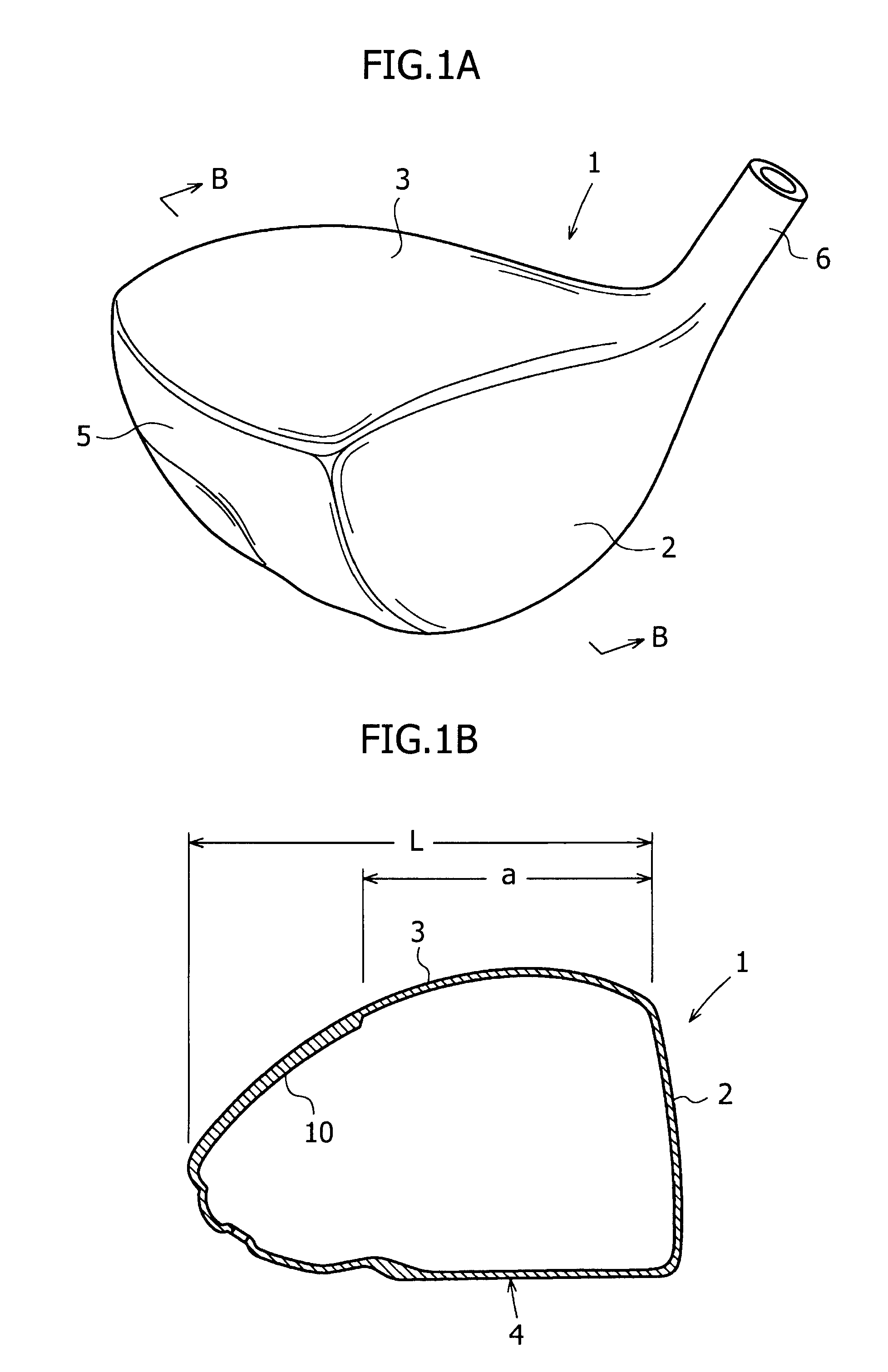
[0046]The dimensions of the thick part 10 were as follows: d=40 mm, b=23 mm, and c=60 mm. The thickness of the thick part 10 was 1.0 mm. The thickness of the crown part 3 was 0.6 mm in the range of e=3.5 mm, and 0.7 mm in the rear half portion (excluding the thick part 10). The thicknesses of the side part 5 and the sole part 4 (excluding a thick part) were 0.8 mm and 0.9 mm, respectively. The face part 2 had a uniform thickness of 3.0 mm as a whole.
[0047]By attaching a shaft to this golf club head, a golf club was formed. The initial velocity, delivery angle,...
PUM
 Abstract
Description
Claims
Application Information