Key button mechanism and an electronic device using the same

a technology of electronic devices and key buttons, applied in the direction of contacts, switch side locations, contact surface shapes/structures, etc., can solve the problems of electrical interference of electronic devices, affecting the overall appearance of electronic devices, and difficult mounting of flexible boards on the mounting portion

Inactive Publication Date: 2009-08-18
CHI MEI COMM SYST INC
View PDF10 Cites 36 Cited by
  • Summary
  • Abstract
  • Description
  • Claims
  • Application Information

AI Technical Summary

Benefits of technology

[0006]Conventional side-buttons include an operating body, a flexible board, and a mounting portion for mounting the flexible board thereon. The mounting portion is arranged on a side surface of an electronic device. When assembled, one end of the flexible board is soldered on a circuit board of the electronic device, and then inversely folded toward the mounting portion to engage with the operating body. However, the above assembly process makes it difficult to mount the flexible board onto the mounting portion. In addition, because the mounting portion is made of plastic material, for being integrally formed with a housing of the electronic device, the static electricity generated during use of the side-buttons may cause electrical interference for the electronic devices.

Problems solved by technology

However, it is difficult to cover this kind of sliding groove, and thus may affect the overall appearance of the electronic devices.
However, the above assembly process makes it difficult to mount the flexible board onto the mounting portion.
In addition, because the mounting portion is made of plastic material, for being integrally formed with a housing of the electronic device, the static electricity generated during use of the side-buttons may cause electrical interference for the electronic devices.

Method used


Image

  • Key button mechanism and an electronic device using the same
  • Key button mechanism and an electronic device using the same
  • Key button mechanism and an electronic device using the same

Examples


Embodiment Construction

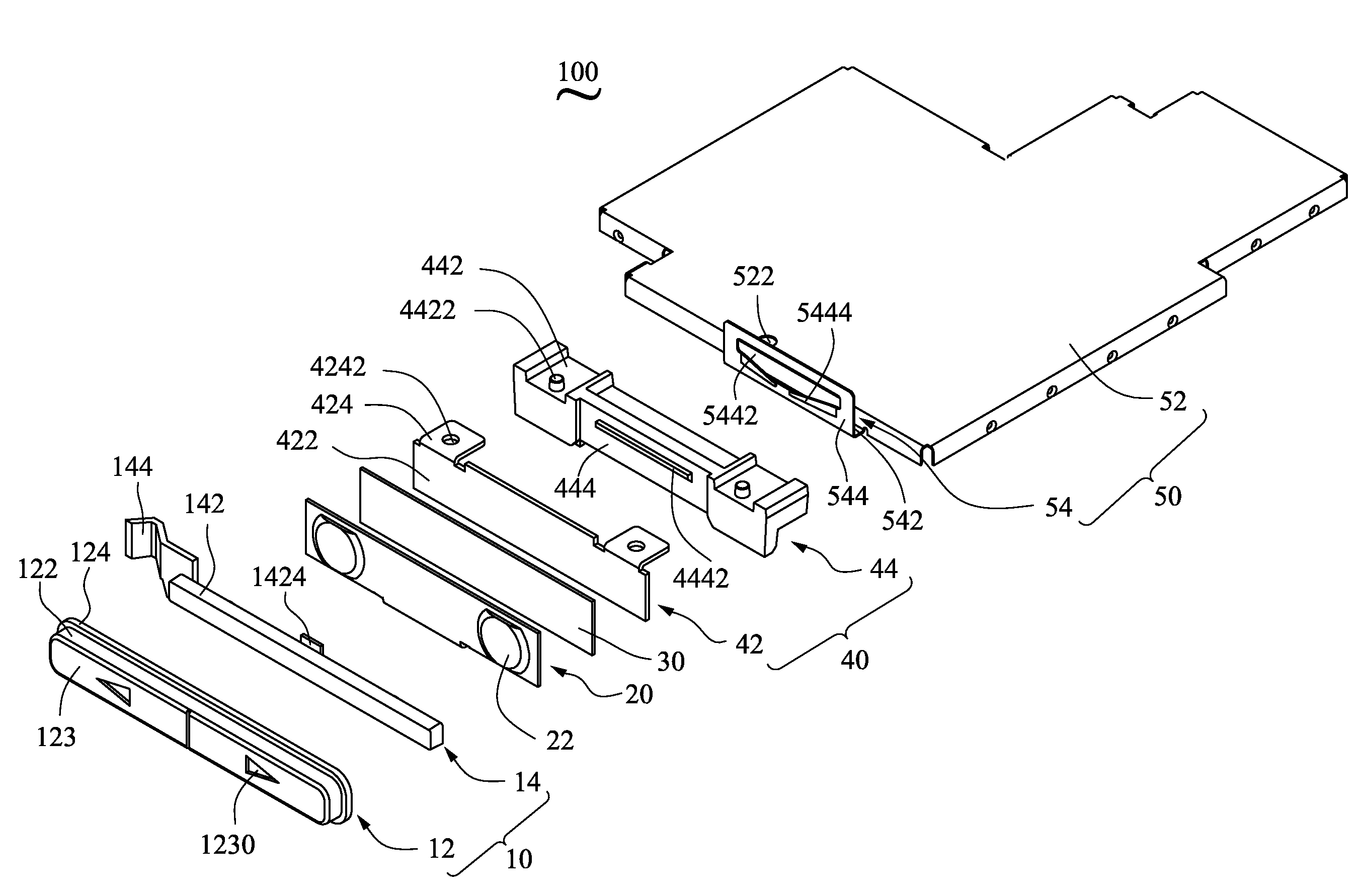
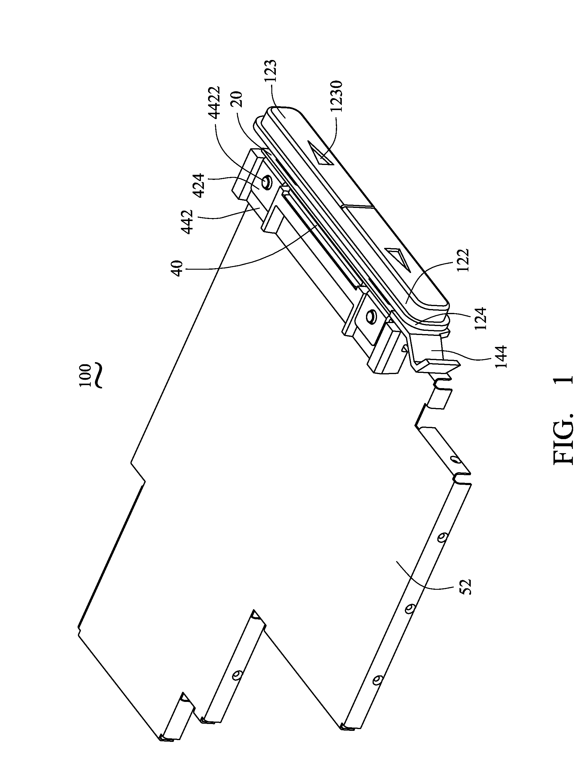
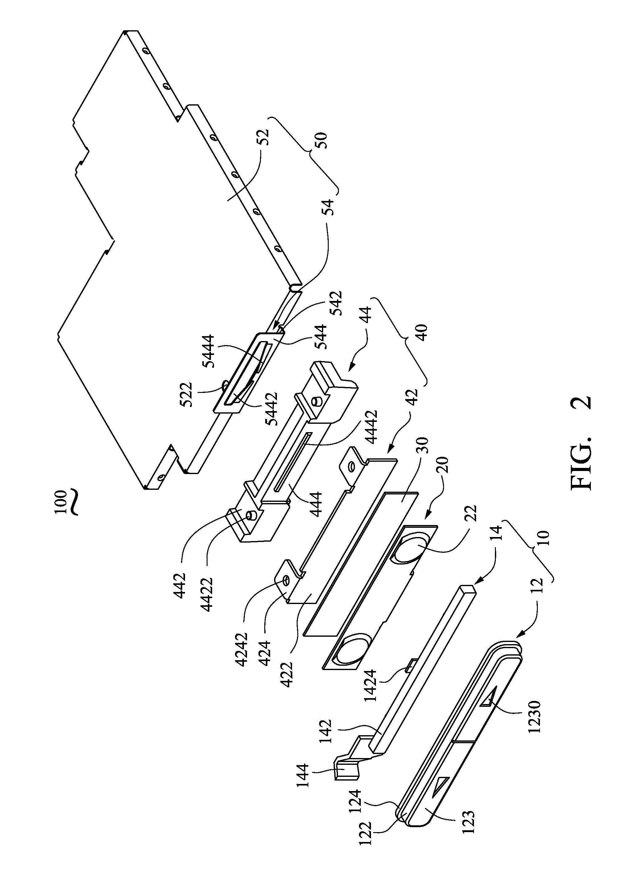
[0014]FIGS. 1-3 show a key button mechanism 100. The key button mechanism 100 includes an operating body 10, a flexible circuit board 20, an adhesive layer 30, a fixing device 40 and a mounting assembly 50.

[0015]The operating body 10 includes an operating cover 12 and a pressing body 14. The operating cover 12 includes a body 122, a pressing surface 123, and a peripheral edge 124. Users may operate the key button mechanism 100 via the pressing surfaces 123. The peripheral edge 124 extends from edges of the body 122 and defines a recessed engaging slot 125 (refer to FIG. 3) for lockably engaging with a housing of an electronic device (not shown).

[0016]The pressing body 14 includes a body portion 142 and an elastic portion 144 connected to one side of the body portion 142. The body portion 142 is substantially rectangular. The size of the body portion 142 equals the size of the engaging slot 125 (FIG. 3) of the operating cover 12 so the body portion 142 may be received in the engaging...


PUM


Abstract

A key button mechanism (100) including an operating body (10), a flexible circuit board (20), a fixing device (40), and a mounting assembly (50) is provided. The flexible circuit board engages with the operating body. The fixing device includes a hanging body (42) and a fixing base (44), and the hanging body is hung on the fixing base. The flexible circuit board is attached to the hanging body. The mounting assembly includes a cover (52) and a mounting portion (54) configured for mounting the fixing base thereon. The hanging body of the fixing device is configured for resisting the mounting portion. An electronic apparatus incorporating the key button mechanism is also provided.

Description

BACKGROUND OF THE INVENTION[0001]1. Field of the Invention[0002]The present invention relates to a key button mechanism and particularly to an electronic device equipped with the key button mechanism.[0003]2. Discussion of the Related Art[0004]With rapid development of information technology, electronic devices, such as cellular phones, personal digital assistant (PDA), and so on, are become more and more popular. For conventional electronic devices, buttons may be arranged on two side surfaces of the electronic devices, hereinafter referred to as side-buttons, and configured for providing command shortcuts. For example, the side-buttons can be used for receiving a call, adjusting sound volume, and so on. Side-button designs significantly contribute to easier operations of the electronic devices.[0005]The general side-buttons of the electronic devices can be sliding structure or pressing structure. For the sliding structure, the side-button slides along a sliding groove to activate ...

Claims


Application Information

Patent Timeline
Patent Type & Authority Patents(United States)
IPC IPC(8): H01H13/02
CPCH01H13/86H01H1/5805H01H2239/008H01H2223/014H01H2225/028H01H2223/012
Inventor TSENG, CHAO-KUNCHAN, KAI-POCHENG, CHAO-YUAN
Owner CHI MEI COMM SYST INC
Why Eureka
Try Eureka