
Foot controlled computer mouse with finger clickers

a computer mouse and foot technology, applied in computing, instruments, electric digital data processing, etc., can solve the problems of reducing the efficiency of the computer operator, confusion if the operator loses his/her place, and inconvenient use of a hand-operated mous

Inactive Publication Date: 2009-08-18
MEDINA CARLOS A
View PDF3 Cites 6 Cited by
  • Summary
  • Abstract
  • Description
  • Claims
  • Application Information

AI Technical Summary

Problems solved by technology

While the use of a hand operated computer mouse to operate commands and to perform various functions on a computer has been well accepted and is now a standard operating component, there are times when the use of a hand operated mouse is inconvenient.
This constant hand movement between the keyboard and mouse reduces the efficiency of the computer operator and, sometimes, results in confusion if the operator loses his / her place on the display.
In other instances, a typist using a word processing program may find it inconvenient and burdensome to constantly remove their hands from the keyboard in order to operate the mouse when entering menu commands needed to perform various functions of the word processing software.

Method used


Image

  • Foot controlled computer mouse with finger clickers
  • Foot controlled computer mouse with finger clickers
  • Foot controlled computer mouse with finger clickers

Examples


Embodiment Construction

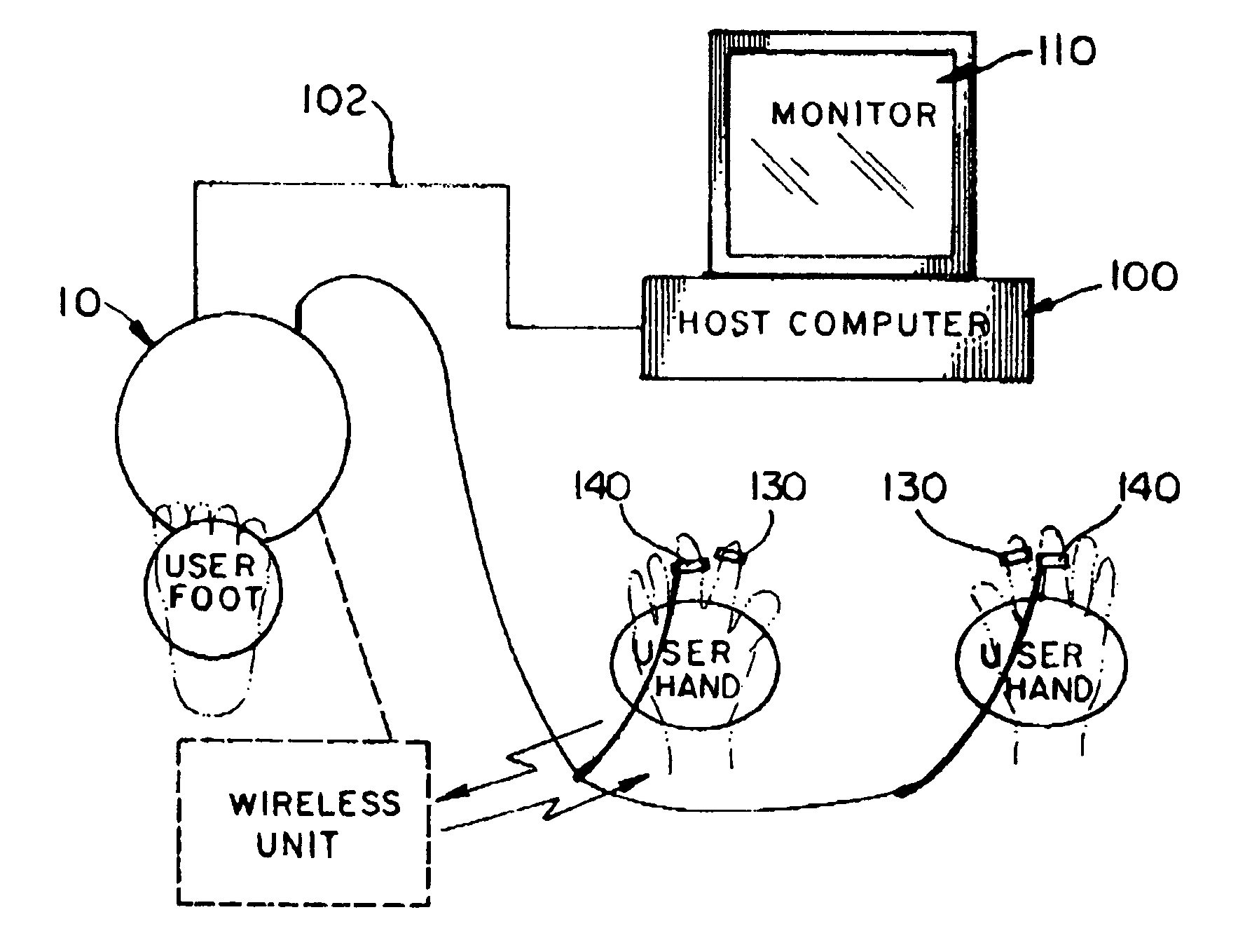
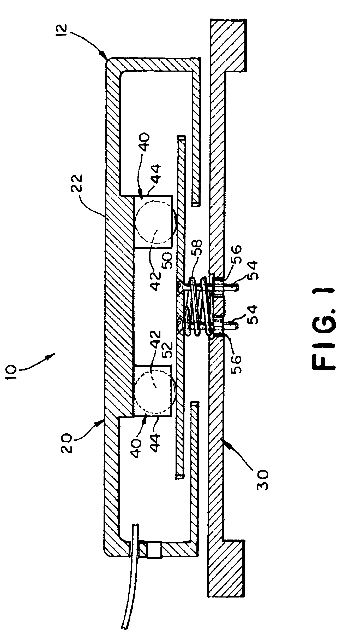
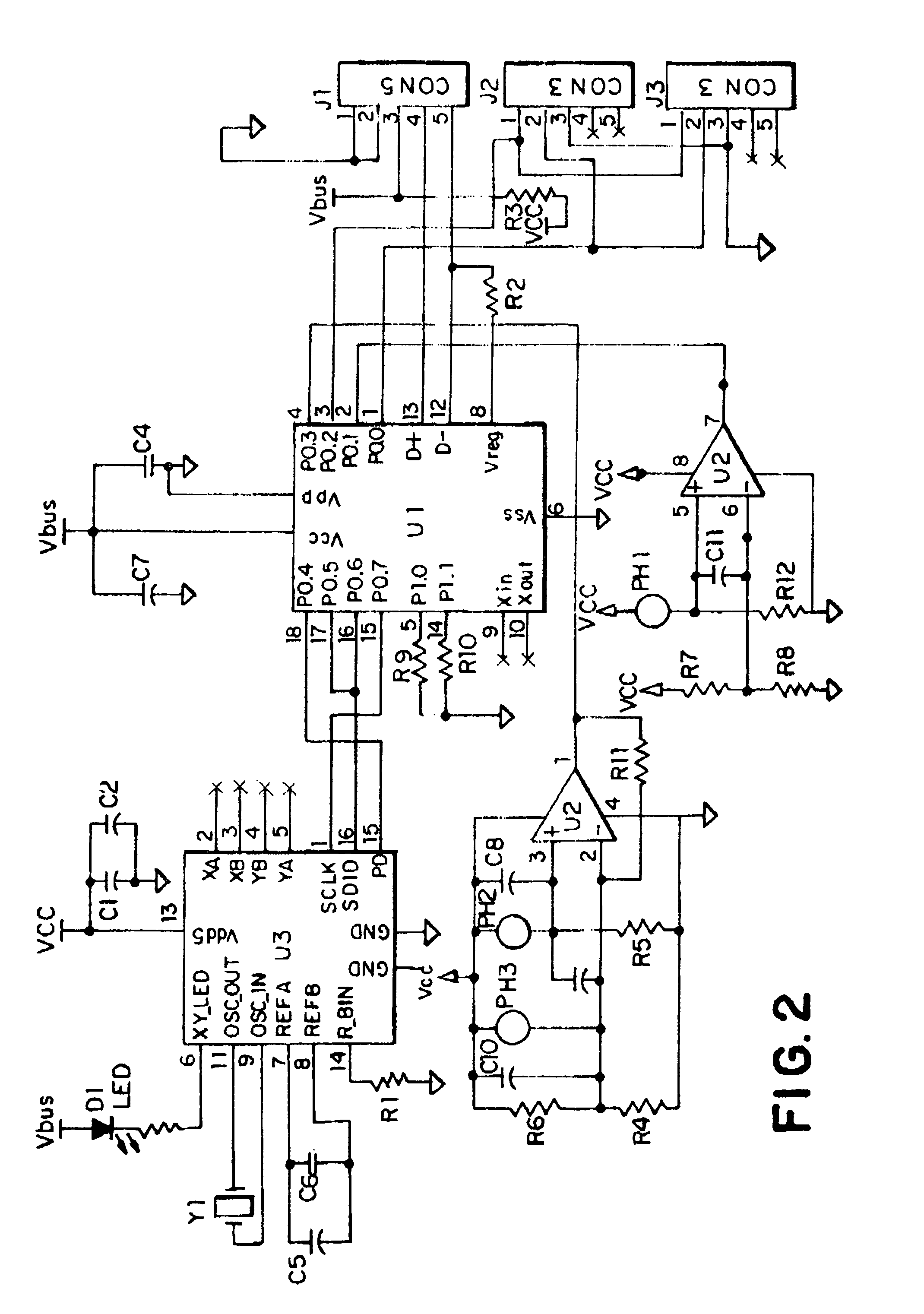
[0015]Referring to the drawings, and initially FIG. 1, the foot controlled computer mouse is shown and is generally indicated as 10. In particular, the foot controlled computer mouse 10 includes a housing 12 having a top portion 20 and a base portion 30. The top portion includes a top foot engaging surface 22 adapted for placement of the user's foot thereon in order to operate the device 10. In use, the top portion 20 is moved relative to the base portion 30 using one's foot by resting the foot on the top surface 22 and urging the top portion 20 in the desired directional movement corresponding with the desired movement of a cursor or other visual indicator on the monitor of a host computer connected to the device 10. In order to promote movement of the top portion 20, roller bearings 40 are provided between the top portion and the base portion 30. More specifically, balls 42 are movably captivated within cylindrical holders 44 extending downwardly from an underside of the top porti...


PUM


Abstract

A device for generating and delivering control signals to a computer has a housing with a top foot engaging surface on a top portion. Roller bearings captivated between the top portion and a base portion are disposed in moving engagement with a plate, thereby allowing the user's foot to move the top portion relative to the base. Optical sensors detect movement of the top portion and transmit electrical signals to a microcontroller which interprets the linear directional movement relative to X and Y coordinates. The user's foot is selectively moved over either a left or right light sensor to perform left and right mouse click operations. An external RCA jack allows for attachment of external cursor control devices, such as hand or finger operated mouse click controls. In one embodiment, magnetic switches are provided in a keyboard to perform left and right click operations, wherein a magnetic ring worn on the hand of the user is selectively passed over either a left or right magnetic switch to perform the left or right click operation. In an alternative embodiment, magnetic switch devices are worn on a finger of the left and right hands and magnetic rings worn on the thumbs are used to selectively perform the left and right click operations by moving the magnetic ring on either the left or right hand in close proximity to the magnetic switch worn on the same hand.

Description

[0001]This patent application is based on provisional patent application Ser. No. 60 / 634,665 filed on Dec. 9, 2004 for which applicant claims the benefit under Title 35, United States Code section 119 (e).BACKGROUND OF THE INVENTION[0002]1. Field of the Invention[0003]The present invention is directed to a foot controlled computer mouse for use independently or in conjunction with hand operated cursor and / or mouse click control devices for delivering control signals to a computer.[0004]2. Discussion of the Related Art[0005]The operating systems of most modern day computers, including the software which runs these computers, is largely dependent on the use of a mouse for moving a pointer or cursor on the display and to activate specific areas and / or icons on the display. Operating systems such as WINDOWS 98, WINDOWS 2000, WINDOWS NT, WINDOWS XP and MAC OS require the user to use a hand operated mouse in order to perform numerous functions for operating the computer and software progr...

Claims


Application Information

Patent Timeline
Patent Type & Authority Patents(United States)
IPC IPC(8): G06F3/033
CPCG06F3/0334
Inventor MEDINA, CARLOS A.
Owner MEDINA CARLOS A
Learn More