Electric drive with expandable catch and protective device

a protective device and electric drive technology, applied in the field of electric drives, can solve the problems of only remotely possible unsatisfactory expansion, and achieve the effect of secure mounting and handling, and without complicated manufacturing equipmen

Active Publication Date: 2009-08-25
BUHLER MOTOR GMBH
View PDF11 Cites 5 Cited by
  • Summary
  • Abstract
  • Description
  • Claims
  • Application Information

AI Technical Summary

Benefits of technology

[0005]It is thus the objective of the invention to present an electric drive which can be securely mounted and handled in an economical manner without additional components and without complicated manufacturing equipment.

Problems solved by technology

This is ensured by the protective device which shields the perceptibly expandable catch means so that an undesired expansion is only remotely possible.

Method used


Image

  • Electric drive with expandable catch and protective device
  • Electric drive with expandable catch and protective device
  • Electric drive with expandable catch and protective device

Examples


Embodiment Construction

[0020]In describing preferred embodiments of the present invention illustrated in the drawings, specific terminology is employed for the sake of clarity. However, the invention is not intended to be limited to the specific terminology so selected, and it is to be understood that each specific element includes all technical equivalents that operate in a similar manner to accomplish a similar purpose.

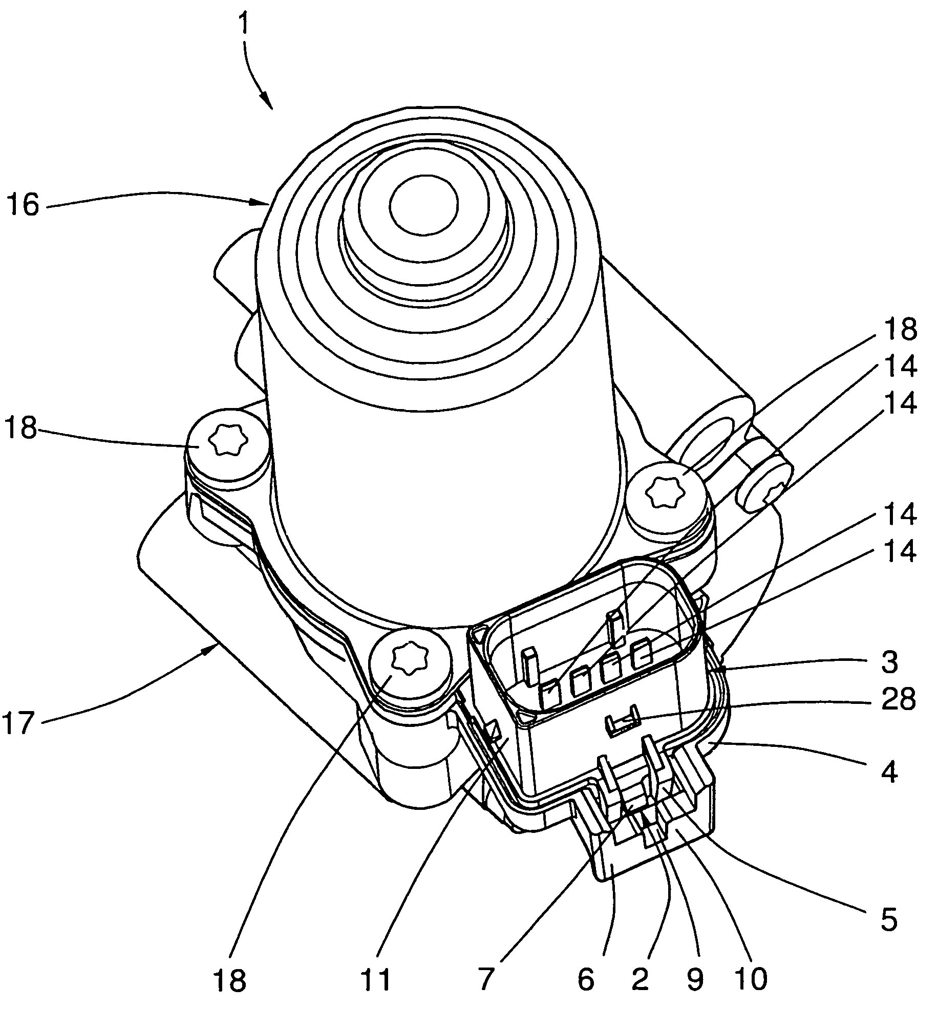
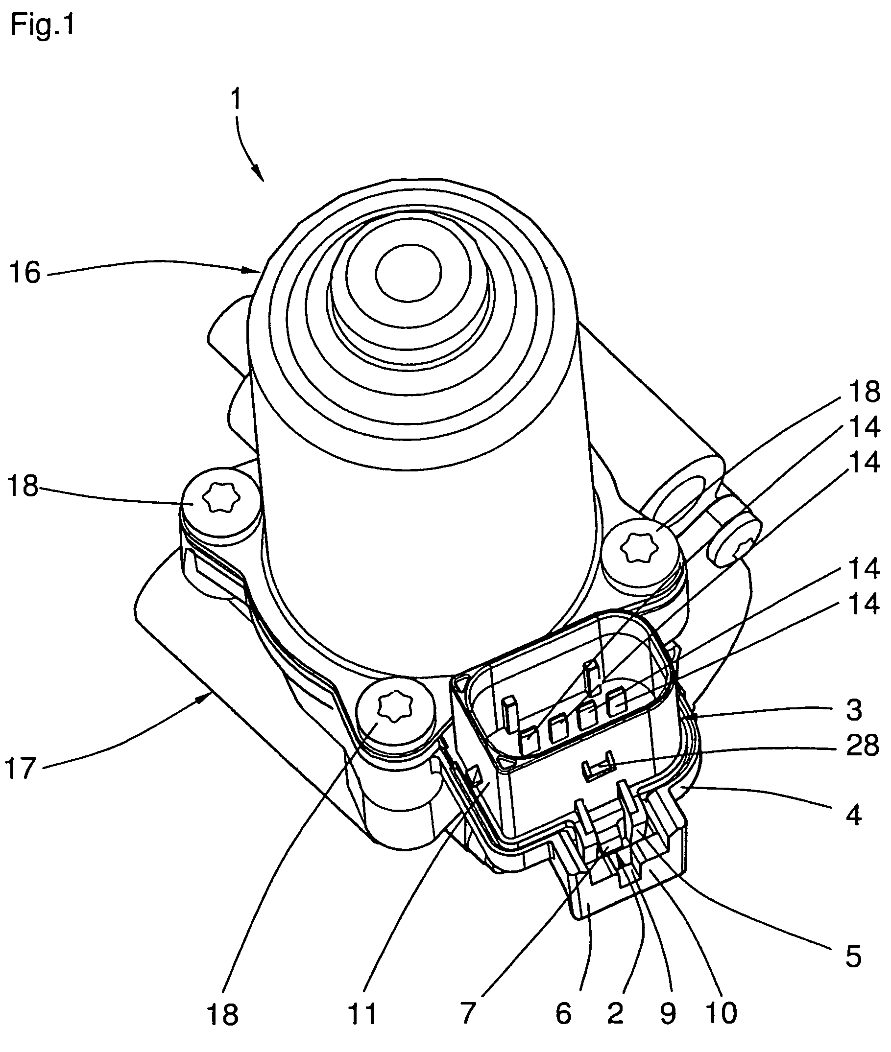
[0021]FIG. 1 shows a three-dimensional view of an electric drive 1 with a first component 3 formed as a brush holder plate and a second component 4 formed as a bearing plate. The brush holder plate is disposed, in the manner of a sandwich, between the housing 16 of an electric motor and the bearing plate 4 which is mechanically connected to a drive housing 17. The motor housing 16, the brush holder plate 3, the bearing plate 4, and the drive housing 17 are interconnected partly via fastening screws 18 and, in the area of a plug housing 11 formed as one piece with the brush holder plate, v...


PUM


Abstract

An electric drive for an electric motor. The electric drive is made up of components consisting of a brush holder plate and a bearing plate which are interconnected via at least one snap-on connector with an expandable catch means that is disposed on an external area of an electric motor, a drive motor, or a positioning drive in such a manner that it projects out. The electric drive can be securely mounted and handled in an economical manner without additional components and without complicated manufacturing equipment. This objective is accomplished by the fact that the expandable catch means is protected by a protective device against unintentional expansion of the catch means and thus loosening of the snap-on connector.

Description

BACKGROUND OF THE INVENTION[0001]1. Field of the Invention[0002]The invention relates to an electric drive, in general, and to an electric drive with components, such as a brush holder plate and as bearing plate, which are interconnected via a novel connector, in particular.[0003]2. Description of Related Art Including Information Disclosed under 37 CFR 1.97 and 1.98[0004]German patent DE 198 13 039 B4 shows a positioning drive where there are two components which are interconnected via several snap-on connectors. Each of the snap-on connectors consists of catch noses and catch eyelets which are completely unprotected and thus it is not possible to rule out damage during handling and mounting. Releasing the connection unintentionally is however hardly possible due to the plurality of snap-on connectors. Applications are also known in which there are only a few snap-on connectors, or even only one, where unintentional loosening or damage of the snap-on means can have serious conseque...

Claims


Application Information

Patent Timeline
Patent Type & Authority Patents(United States)
IPC IPC(8): H02K5/00
CPCH02K5/148H02K5/225H02K2211/03
Inventor GUTTENBERGER, RICHARD
Owner BUHLER MOTOR GMBH
Why Eureka
Try Eureka