Closure having a seal piercing unit

Active Publication Date: 2014-06-10
BERLIN PACKAGING
View PDF31 Cites 12 Cited by
  • Summary
  • Abstract
  • Description
  • Claims
  • Application Information

AI Technical Summary

Benefits of technology

[0010]These, and other, objects are achieved by a container closure unit which opens a seal covering an discharge port of a container and which is removed after the seal has been opened. The closure unit has a seal piercing unit releasably mounted on a base element by a tearable connection and which includes knife-like elements mounted on a flexible dome-shaped base to be positioned adjacent to the seal when the base element is secured to the container. The flexible dome-shaped base is initially convex with respect to the seal, but is flexed into a concave orientation when a user pushes the dome-shaped base toward the seal. This pushing forces the knife-like elements into contact with the seal, and then the curvature change of the dome-shaped base causes those knife-like elements to pierce the seal and tear slits in the seal. The slits will act as fluid passages during decanting of the fluid from the container. Once the seal has been punctured, the seal piercing unit is removed from the base using a pull ring mounted on the dome-shaped base. The pull ring is grasped and pulled away from the container and the dome-shaped base is torn out of the base element along the tearable connection. The dome-shaped base and the

Problems solved by technology

Manual removal of the seal can be cumbersome, annoying and, in some cases, not possible.
If a user has impaired finger dexterity or large fingers, such seal removal can be difficult if not impossible.
Such seal openers however do not function satisfactorily.
On dispensing of the product, the shreds may block or impede the path of the outflowing product.
This problem is exacerbated in large packages which may have large and strong seals.
In some seals, particularly large seals, the seal may flex under the influence of the cutter and impede the cutting action of the remainder of the seal.
While the art has suggested pre-weakening such seals at selected locations in order to expedite the seal cutting or tearing process, such suggestions are expensive and may require expensive installations and handling during the production process.
Even then, the devices which are intended to open a seal by cutting with teeth can remain inefficient and ineffective.
Still further, if a consumer is required to remove a cap from a container and then manipulate that cap in order to break a seal, the design will be disadvantaged.
The consumer may drop the cap, or become annoyed by the extra steps associated with opening a container or the like

Method used


Image

  • Closure having a seal piercing unit
  • Closure having a seal piercing unit
  • Closure having a seal piercing unit

Examples


Embodiment Construction

[0036]Other objects, features and advantages of the invention will become apparent from a consideration of the following detailed description and the accompanying drawings.

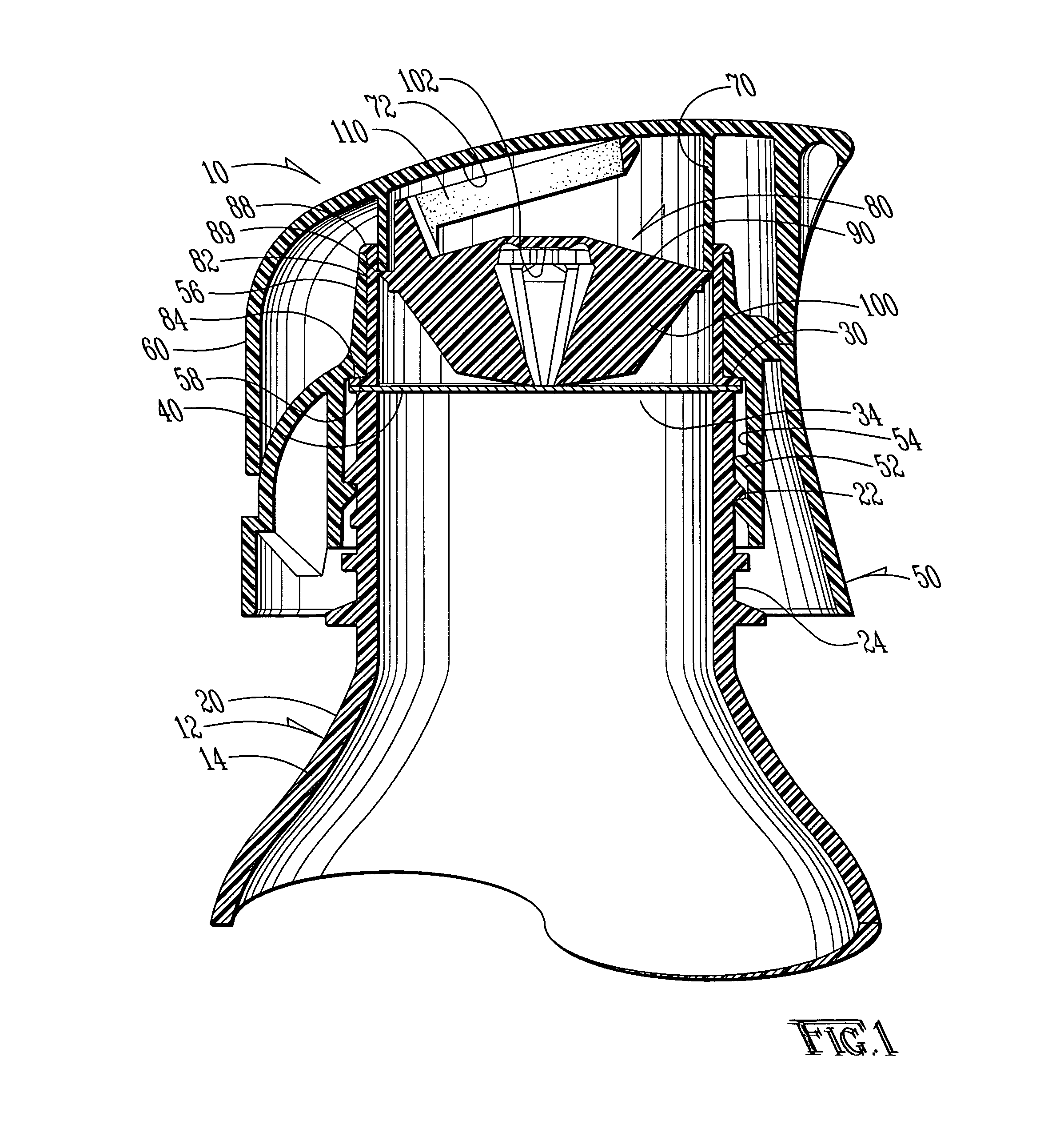
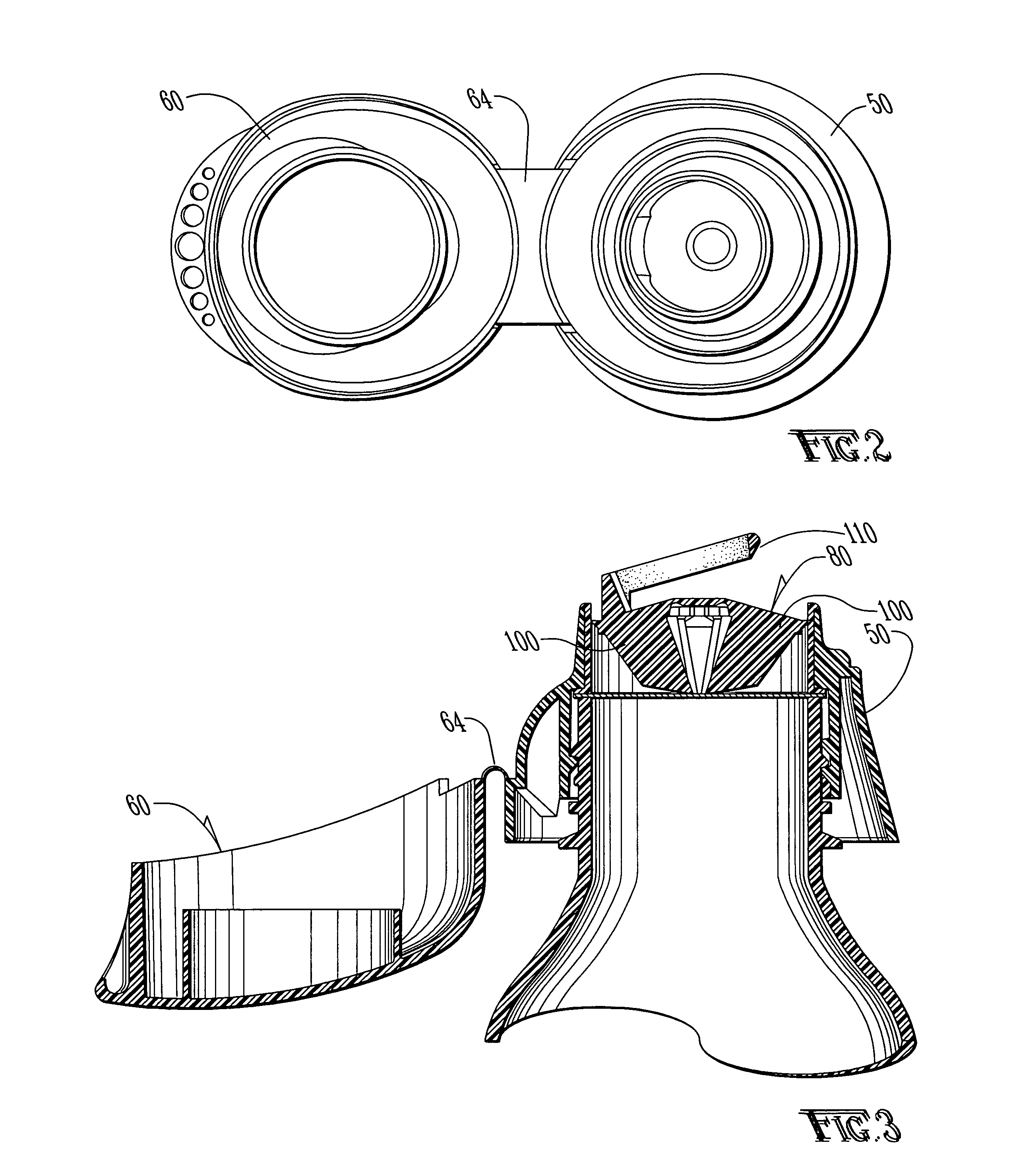
[0037]Referring to FIGS. 1-3, it can be understood that the principles of the present invention are embodied in a closure cap 10 which is used to close a container 12 such as a bottle or the like, having a body 14 on which a neck finish 20 is surmounted. An external thread 22 is located on outside surface 24 of the neck finish and a top rim 30 is located on top of the neck finish when the container is in the upright orientation shown in FIG. 1 and defines a decanting port 34 through which fluid from the internal volume 36 of the container is discharged from the container. A seal 40 is located on the top rim to span port 34 to sealingly close that port. Seal 40 must be punctured or torn in order to decant the fluid from the container.

[0038]Closure cap 10 acts as an initial closure of the container and as a means fo...


PUM


Abstract

A seal covering a discharge port of a container is opened without leaving superfluous elements on the container by a container closure unit which has seal-piercing knife-like elements mounted on a flexible dome-shaped base which is located to place the knife-like elements adjacent to the seal. The dome-shaped base is flexed to move the knife-like elements through the seal and then to move them outwardly toward the periphery of the seal to cut slits in the seal. The slits act as fluid passages to permit decanting of the fluid from the container. Once the seal has been opened, the dome-shaped base is removed using a pull ring and discarded. The container closure unit has a cap which is used to close the container discharge port between uses.

Description

TECHNICAL FIELD OF THE INVENTION[0001]The present invention relates to the general art of containers, and to the particular field of container closures.CROSS REFERENCE TO RELATED APPLICATION[0002]This application claims the benefit of the filing date of Provisional Patent Application Ser. No. 61 / 207,678, filed on Feb. 13, 2009 filed by the same inventor.BACKGROUND OF THE INVENTION[0003]Often, containers are encountered which have, in addition to a screw cap, a seal or film over the opening which is designed to provide security from and / or evidence of tampering, reduce bacterial infection, prevent volatile liquid from evaporating, prevent fluid from leaking out of the container, prevent oxygen or other contaminants from entering the container, or otherwise protect the product. Commonly these include sealed containers for medicine, glue and the like where a plastic container top is actually sealed closed during the molding process. Other examples include containers which contain table...

Claims


Application Information

Patent Timeline
IPC IPC(8): B65D39/00B65D47/36B65D47/00
CPCB65D51/2835B65D47/36B65D51/00
Inventor CLAUSE, MARKNIGGEL, BRETT
Owner BERLIN PACKAGING
Why Eureka
Try Eureka