Dynamic bandwidth allocation to transmit a wireless protocol across a code division multiple access (CDMA) radio link

a wireless protocol and radio link technology, applied in data switching networks, time-division multiplexing selection, orthogonal multiplex, etc., can solve the problems of inability to adapt to the voice grade service available in most homes or offices, the typical way of providing high speed data service in the business environment over the wireline network, and the inability to efficiently transmit over standard cellular wireless handsets. to achieve the effect of more efficient channel setup and tear down

Inactive Publication Date: 2009-08-25
INTEL CORP
View PDF166 Cites 15 Cited by
  • Summary
  • Abstract
  • Description
  • Claims
  • Application Information

AI Technical Summary

Benefits of technology

[0017]In a preferred arrangement, a single subchannel is maintained for a predetermined minimum idle time for each network layer connection. This assists with more efficient management of channel setup and tear down.

Problems solved by technology

For example, in the late 1980's, wireless voice communication such as available with cellular telephony had been the exclusive province of the businessman because of expected high subscriber costs.
There still is no widely available satisfactory solution for providing low cost, high speed access to the Internet and other networks using existing wireless networks.
For example, the typical manner of providing high speed data service in the business environment over the wireline network is not readily adaptable to the voice grade service available in most homes or offices.
In addition, such standard high speed data services do not lend themselves well to efficient transmission over standard cellular wireless handsets.
Although such networks were known at the time that cellular systems were originally deployed, for the most part, there is no provision for providing ISDN-grade data services over cellular network topologies.
Unfortunately, in wireless environments, access to channels is expensive and there is competition for them; the nature of the medium is such that they are expected to be shared.

Method used


Image

  • Dynamic bandwidth allocation to transmit a wireless protocol across a code division multiple access (CDMA) radio link
  • Dynamic bandwidth allocation to transmit a wireless protocol across a code division multiple access (CDMA) radio link
  • Dynamic bandwidth allocation to transmit a wireless protocol across a code division multiple access (CDMA) radio link

Examples


Embodiment Construction

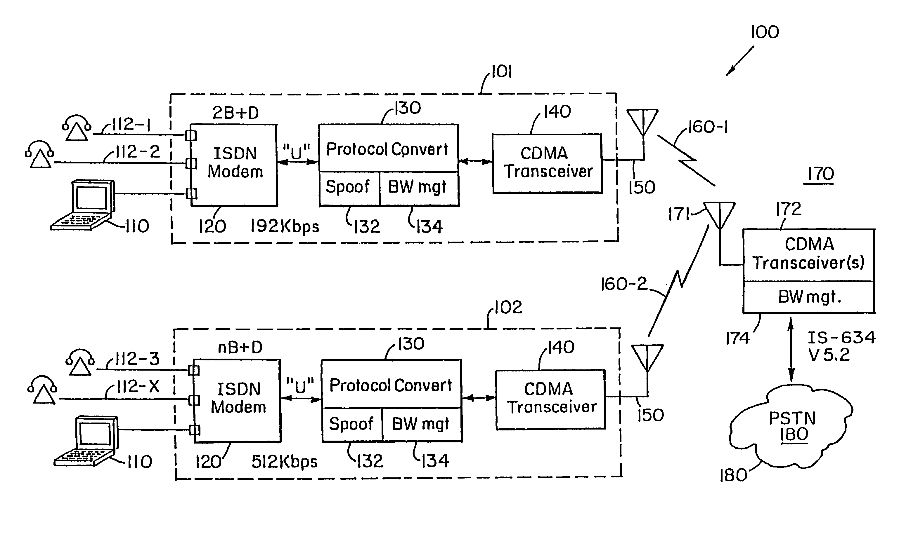
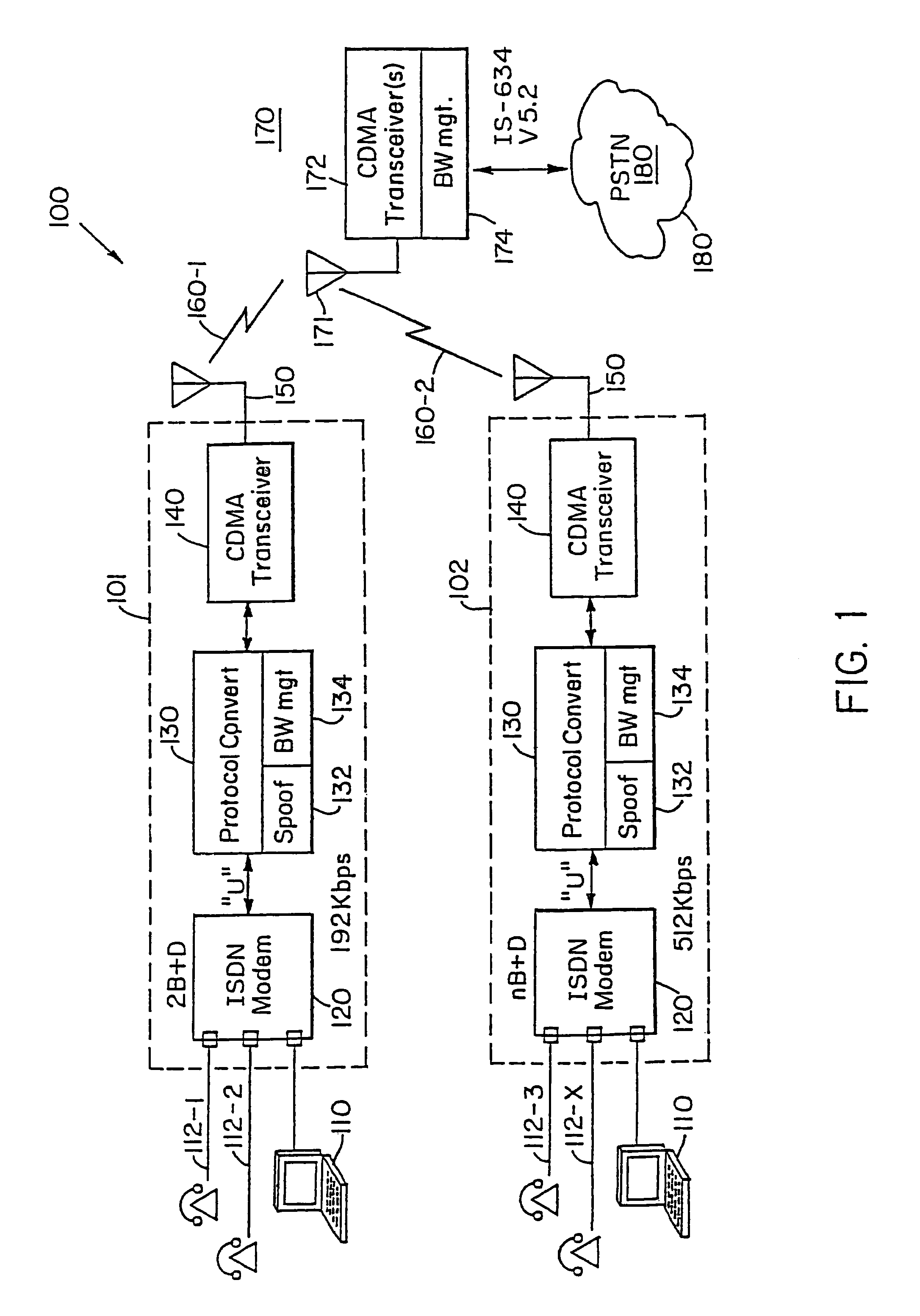
[0026]Turning attention now to the drawings more particularly, FIG. 1 is a block diagram of a system 100 for providing high speed data and voice service over a wireless connection by seamlessly integrating a digital data protocol such as, for example, Integrated Services Digital Network (ISDN) with a digitally modulated wireless service such as Code Division Multiple Access (CDMA).

[0027]The system 100 consists of two different types of components, including subscriber units 101, 102 and base stations 170. Both types of these components 101 and 170 cooperate to provide the functions necessary in order to achieve the desired implementation of the invention. The subscriber unit 101 provides wireless data services to a portable computing device 110 such as a laptop computer, portable computer, personal digital assistant (PDA) or the like. The base station 170 cooperates with the subscriber unit 101 to permit the transmission of data between the portable computing device 110 and other de...


PUM


Abstract

A code division multiple access (CDMA) user device includes a CDMA transceiver, and a controller connected to the CDMA transceiver for establishing a communication session with a base station. The communication session includes a plurality of layers including a physical layer. The controller negotiates with the base station for an allocated bandwidth for the CDMA transceiver. The controller also establishes and releases a physical layer connection between the CDMA transceiver and the base station, and maintains a state of at least one other layer during the communication session after termination of the physical layer.

Description

CROSS REFERENCE TO RELATED APPLICATIONS[0001]This application is a Continuation of U.S. application Ser. No. 10 / 345,791 filed Jan. 16, 2003, now abandoned entitled “Dynamic Bandwidth Allocation to Transmit a Wireless Protocol Across a Code Division Multiple Access (CDMA) Radio Link, which is a Continuation of U.S. application Ser. No. 09 / 596,425, filed Jun. 19, 2000, now U.S. Pat. No. 6,526,281 entitled “Dynamic Bandwidth Allocation to Transmit a Wireless Protocol Across a Code Division Multiple Access (CDMA) Radio Link,” which in turn is a Continuation of U.S. application Ser. No. 08 / 992,760, filed Dec. 17, 1997, now U.S. Pat. No. 6,081,536 entitled “Dynamic Bandwidth Allocation to Transmit a Wireless Protocol Across a Code Division Multiple Access (CDMA) Radio Link,” which itself claims the benefit of U.S. Provisional Application No. 60 / 050,338 filed Jun. 20, 1997 entitled “Dynamic Bandwidth Allocation to Transmit a Wireless Protocol Across a Code Division Multiple Access (CDMA) R...

Claims


Application Information

Patent Timeline
Patent Type & Authority Patents(United States)
IPC IPC(8): H04W72/00H04B7/26H04B7/212H04J3/16H04J11/00H04J13/16H04J13/18H04L1/16H04L12/56H04Q11/04H04W28/22H04W72/04H04W72/12H04W80/00H04W84/04H04W84/14
CPCH04J13/16H04L1/165H04Q11/0428H04W28/22H04W72/0453H04W72/0466H04J13/18H04W72/00H04Q2213/13098H04Q2213/13176H04Q2213/13202H04Q2213/13204H04Q2213/13209H04Q2213/13216H04Q2213/1327H04Q2213/13294H04Q2213/13298H04Q2213/13332H04Q2213/1336H04Q2213/13389H04W80/00H04W84/042H04W84/14H04W76/30
Inventor GORSUCH, THOMAS E.AMALFITANO, CARLO
Owner INTEL CORP
Why Eureka
Try Eureka