Radar level gauge system using a waveguiding structure with periodically arranged reference impedance transitions

Active Publication Date: 2009-09-08
ROSEMOUNT TANK RADAR
View PDF7 Cites 57 Cited by
  • Summary
  • Abstract
  • Description
  • Claims
  • Application Information

AI Technical Summary

Benefits of technology

[0012]In view of the above-mentioned and other drawbacks of the prior art, a general object of the present invention is to provide an improved ra

Problems solved by technology

Typically, the calibration echoes are either too strong and disturb the fi

Method used


Image

  • Radar level gauge system using a waveguiding structure with periodically arranged reference impedance transitions
  • Radar level gauge system using a waveguiding structure with periodically arranged reference impedance transitions
  • Radar level gauge system using a waveguiding structure with periodically arranged reference impedance transitions

Examples


Embodiment Construction

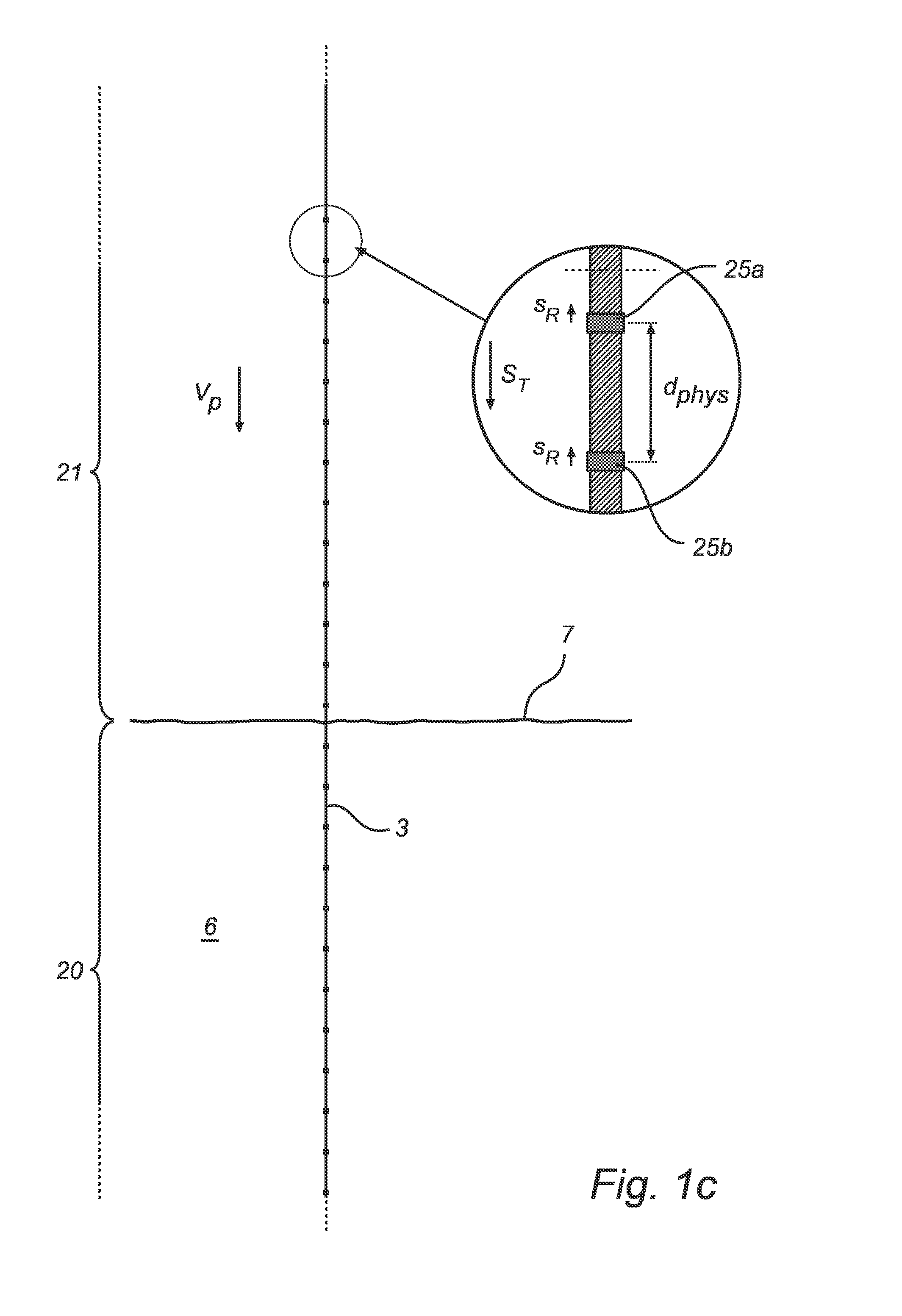
[0059]In the present detailed description, various embodiments of the radar level gauge system according to the present invention are mainly discussed with reference to a guided wave radar (GWR) level gauge system of the FMCW (Frequency Modulated Continuous Wave) type utilizing a single line probe. It should be noted that this by no means limits the scope of the present invention, which is equally applicable to radar level gauge systems including various other kinds of waveguiding structures, such as twin-line probes, coaxial probes, still pipes, etc. Furthermore, the present invention is not limited to radar level gauge systems of the FMCW-type, but may equally well be implemented in pulsed radar level gauge systems, in which the received echo pulses can be analyzed to determine the frequency of the reference signal and hence the propagation velocity in the medium inside the tank above the surface of the product contained therein.

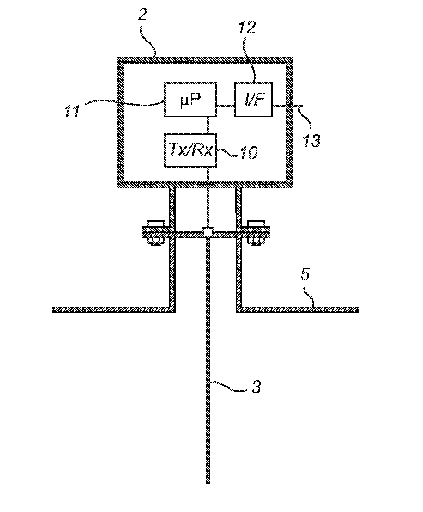
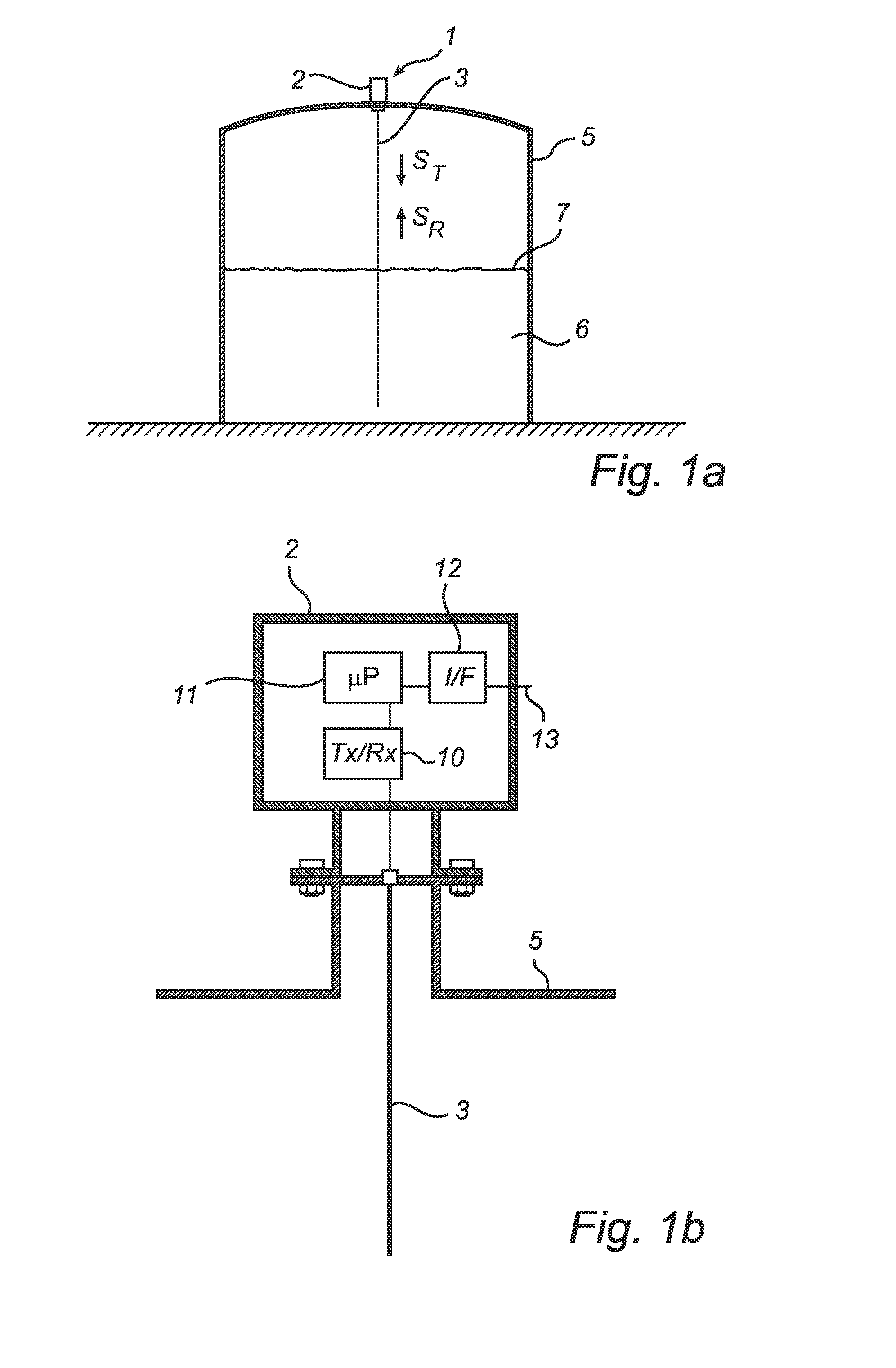
[0060]FIG. 1a schematically illustrates a radar leve...


PUM


Abstract

A radar level gauge system, for determining a filling level of a product contained in a tank, said radar level gauge system comprising:
    • a transceiver for generating, transmitting and receiving electromagnetic signals within a frequency range;
    • a waveguiding structure arranged to extend into said product contained in the tank and to guide a transmitted signal from said transceiver towards a surface of said product and to guide echo signals resulting from reflections at impedance transitions encountered by the transmitted electromagnetic signals, including a surface echo signal resulting from reflection at said surface, back to said transceiver;
    • a plurality of reference impedance transitions provided substantially periodically along said waveguiding structure with a distance between adjacent reference impedance transitions that is selected such that signals resulting from reflection of said transmitted signal at each of said reference impedance transitions combine to form a reference signal having a frequency within said frequency range; and
    • processing circuitry connected to said transceiver for determining a propagation velocity of said electromagnetic signals in a medium inside the tank above said surface of the product based on said frequency of said reference signal and said distance between adjacent reference impedance transitions, and determining said filling level based on said surface echo signal and said propagation velocity.

Description

TECHNICAL FIELD OF THE INVENTION[0001]The present invention relates to a radar level gauge system using a waveguiding structure, such as a probe or a still pipe, for determining a filling level of a product contained in a tank.TECHNICAL BACKGROUND[0002]Radar level gauge (RLG) systems are in wide use for determining the filling level of a product contained in a tank. Radar level gauging is generally performed either by means of non-contact measurement, whereby electromagnetic signals are radiated towards the product contained in the tank, or by means of contact measurement, often referred to as guided wave radar (GWR), whereby electromagnetic signals are guided towards and into the product by a waveguiding structure, such as a probe or a still pipe. The waveguiding structure is generally arranged to extend vertically from the top towards the bottom of the tank. The waveguiding structure may also be arranged in a measurement tube, a so-called chamber, that is connected to the outer wa...

Claims


Application Information

Patent Timeline
IPC IPC(8): G01S13/08G01F25/00
CPCG01F23/284G01S7/4052G01S7/4056G01S13/88G01S2007/4078G01S7/4078
Inventor EDVARDSSON, OLOV
Owner ROSEMOUNT TANK RADAR
Why Eureka
Try Eureka