System and method for filling level determination

a filling level and level determination technology, applied in the field of radar level gauge system, can solve the problems of small impedance transition, low accuracy, and relatively weak echo signal, and achieve the effect of high accuracy filling level determination

Active Publication Date: 2010-06-24
ROSEMOUNT TANK RADAR
View PDF26 Cites 59 Cited by
  • Summary
  • Abstract
  • Description
  • Claims
  • Application Information

AI Technical Summary

Benefits of technology

[0013]In view of the above-mentioned and other drawbacks of the prior art, a general object of the present invention is to provide an improved radar level gauge system and method, and in particular a radar level gauge system and method capable of higher accuracy filling level determination.

Problems solved by technology

There is therefore a certain risk that the system attempts to determine the filling level based on the wrong reflected signal.
This results in a small impedance transition and, accordingly, a relatively weak echo signal.
Beside of having low reflection these liquids are transparent for radar waves so an echo below the surface will be visible through the surface as well and may interfere with the surface echo.
Typical radar level gauging systems can distinguish between echoes which are at least a few dm to half a meter apart and for liquids having a small attenuation (a few dB) over such a distance close echoes can be mixed up resulting in considerable errors in the measured distance while the surface is moving.
However, such a disturbance echo profile can then only be reliably determined above the surface of the product contained in the container, because of the relatively stable propagation characteristics in the atmosphere above the surface of the product.
Under certain conditions such as in case with close and strongly disturbing echoes, it may, however, be difficult to determine the surface echo signal, which may result in that the surface echo signal is included in the disturbance echo profile when the method disclosed in U.S. Pat. No. 6,078,280 is used, which may lead to an incorrect filling level determination.

Method used


Image

  • System and method for filling level determination
  • System and method for filling level determination
  • System and method for filling level determination

Examples


Embodiment Construction

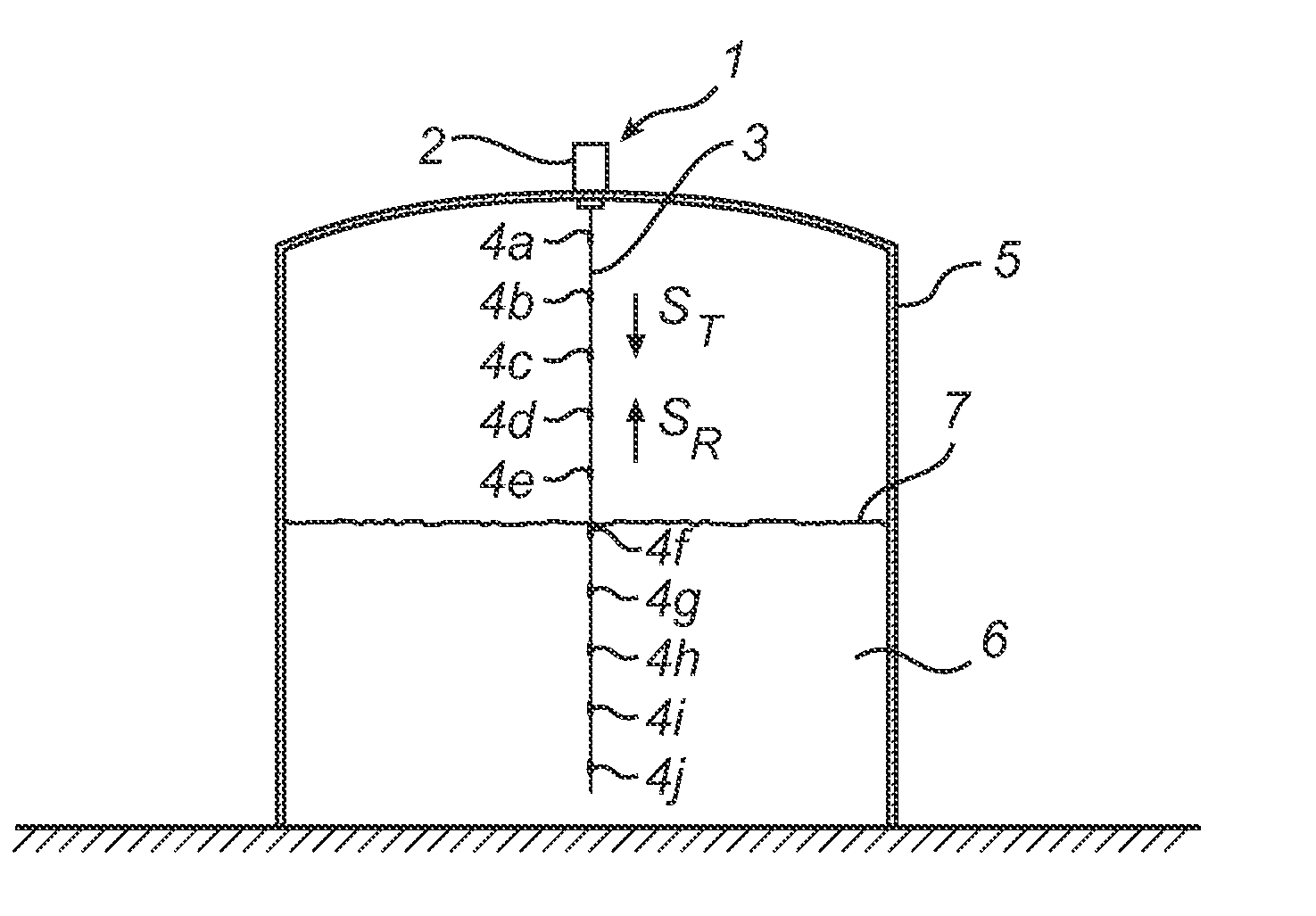
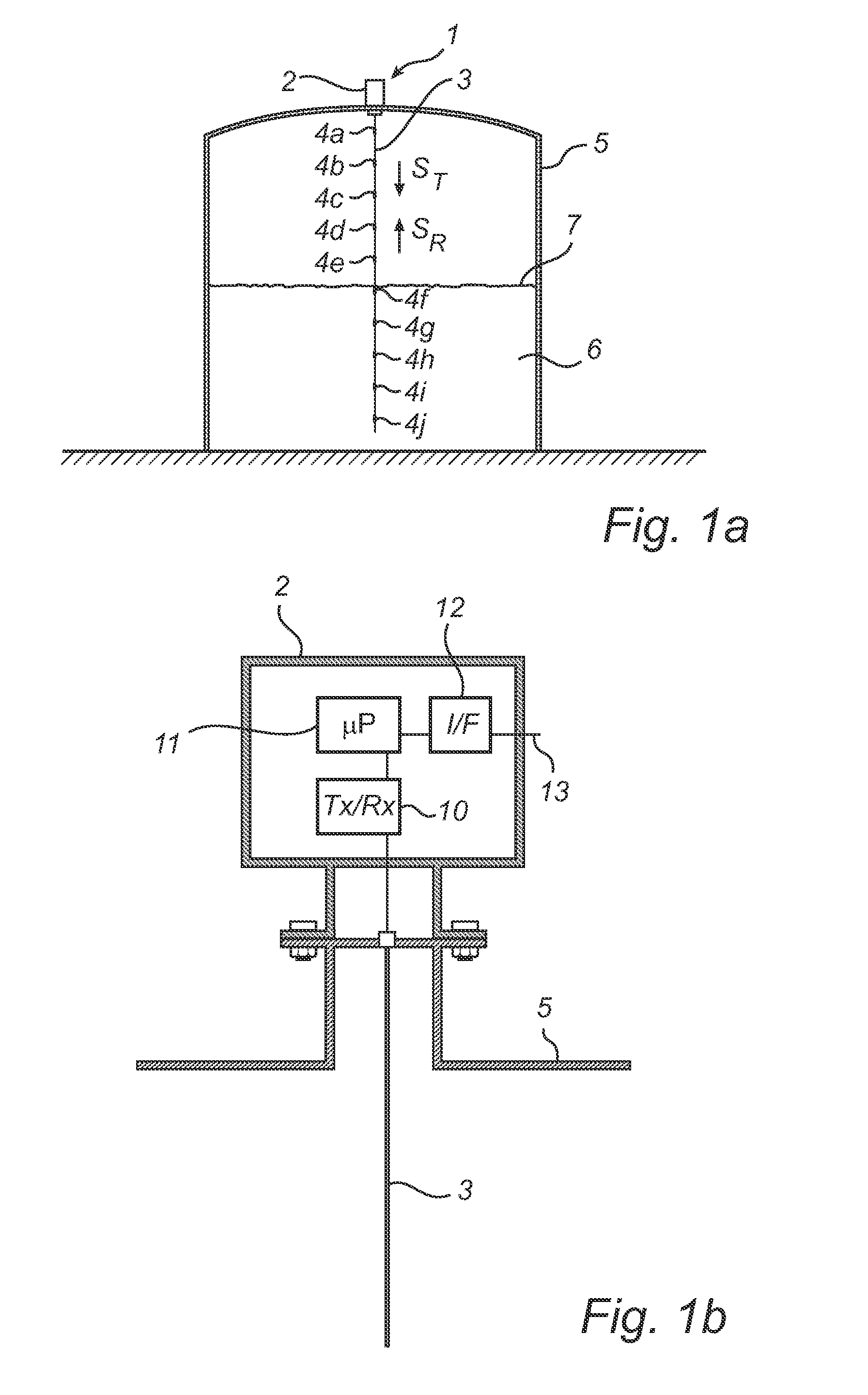
[0049]In the present detailed description, various embodiments of the radar level gauge system according to the present invention are mainly discussed with reference to a pulsed guided wave radar (GWR) level gauge system utilizing a rigid single line (or Goubau) probe. It should be noted that this by no means limits the scope of the present invention, which is equally applicable to various other kinds of probes, such as two-lead probes, flexible probes, etc.

[0050]Furthermore, reference is mainly made to filling level determination by means of measuring the time between transmitted and reflected pulses. As is, however, evident to the person skilled in the relevant art, the teachings of the present invention are equally applicable to radar level gauge systems utilizing phase information for determining the filling level through, for example, frequency-modulated continuous wave (FMCW) measurements. When pulses modulated on a carrier are used, phase information can also be utilized.

[005...


PUM


Abstract

A radar level gauge system using microwaves for measuring a level of a surface of a product in a container, comprising a waveguide arranged to extend into the product contained in the container, wherein a plurality of reference impedance transitions are arranged at known position along the waveguide and being configured to reflect a portion of transmitted electromagnetic signals back towards the transceiver. Preferably, each of the reference impedance transitions has a first reflection coefficient for the electromagnetic signals when the level of the surface is above the reference impedance transition and a second reflection coefficient for the electromagnetic signal when the level of the surface is below the reference reflector, the first reflection coefficient being substantially lower than the second reflection coefficient. According to this design, a higher accuracy of filling level measurements can be achieved.

Description

TECHNICAL FIELD OF THE INVENTION [0001]The present invention relates to a radar level gauge system using a waveguide, such as a single-line of Goubau-type, for determining a filling level of a product contained in a container.TECHNICAL BACKGROUND [0002]Radar level gauge (RLG) systems are in wide use for determining the filling level of a product contained in a container, such as a tank. Radar level gauging is generally performed either by means of non-contact measurement, whereby electromagnetic signals are radiated towards the product contained in the container, or by means of contact measurement, often referred to as guided wave radar (GWR), whereby electromagnetic signals are guided towards and into the product by a probe acting as a waveguide, such as a probe. The probe is generally arranged to extend vertically from the top towards the bottom of the container. The probe may also be arranged in a measurement tube, a so-called bridle, which is connected to the outer wall of the c...

Claims


Application Information

Patent Timeline
Patent Type & Authority Applications(United States)
IPC IPC(8): G01S13/08
CPCG01F23/284G01S7/2921G01S2007/4078H01Q13/02G01S7/4056H01Q1/225G01S7/4078G01S7/4052G01S13/88
Inventor EDVARDSSON, OLOV
Owner ROSEMOUNT TANK RADAR
Why Eureka
Try Eureka