Supercharge Your Innovation With Domain-Expert AI Agents!

Variable speed ratio transmission

a transmission and variable speed technology, applied in the field of transmission, can solve the problems of power source stalling and powering the transmission, power source stalling, and power source stalling

Inactive Publication Date: 2009-09-29
FERRAR PHILIP T
View PDF50 Cites 3 Cited by
  • Summary
  • Abstract
  • Description
  • Claims
  • Application Information

AI Technical Summary

Benefits of technology

Enables continuous variable speed ratios and extended operation without slippage or maintenance, allowing speed ratio changes while stationary and accommodating wear, thus enhancing the transmission's viability and performance.

Problems solved by technology

However, most of these conventional infinitely variable transmissions do not permit the speed ratio to be changed while the input and the output are standing still.
As a result, when the required input torque becomes too great for the power source providing the torque to the input, the power source may stall and cease powering the transmission.
If the transmission is mounted in a vehicle and the speed ratio is set too high so the required input torque is too high for the power source to turn the input, the power source may stall and the vehicle will become immobile.
If the speed ratio cannot be changed while the transmission is standing still, the required input torque cannot be adjusted downward thereby preventing the vehicle from overcoming its immobility.
Internal parts in some infinitely variable transmissions become worn early in the transmission life.
As a result, some variable speed transmissions may require early maintenance and / or part replacement so they can adequately transmit torque.
In many instances early maintenance or part replacement make infinitely variable transmissions non-viable.

Method used


Image

  • Variable speed ratio transmission
  • Variable speed ratio transmission
  • Variable speed ratio transmission

Examples


Embodiment Construction

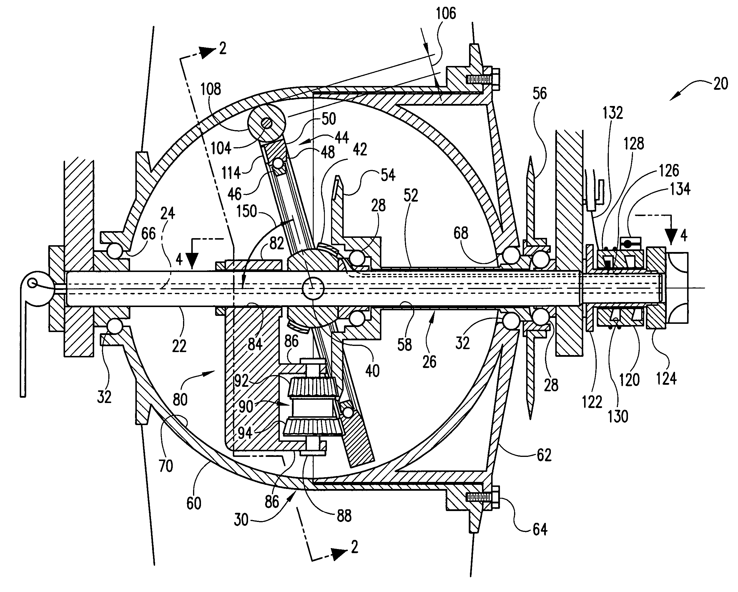
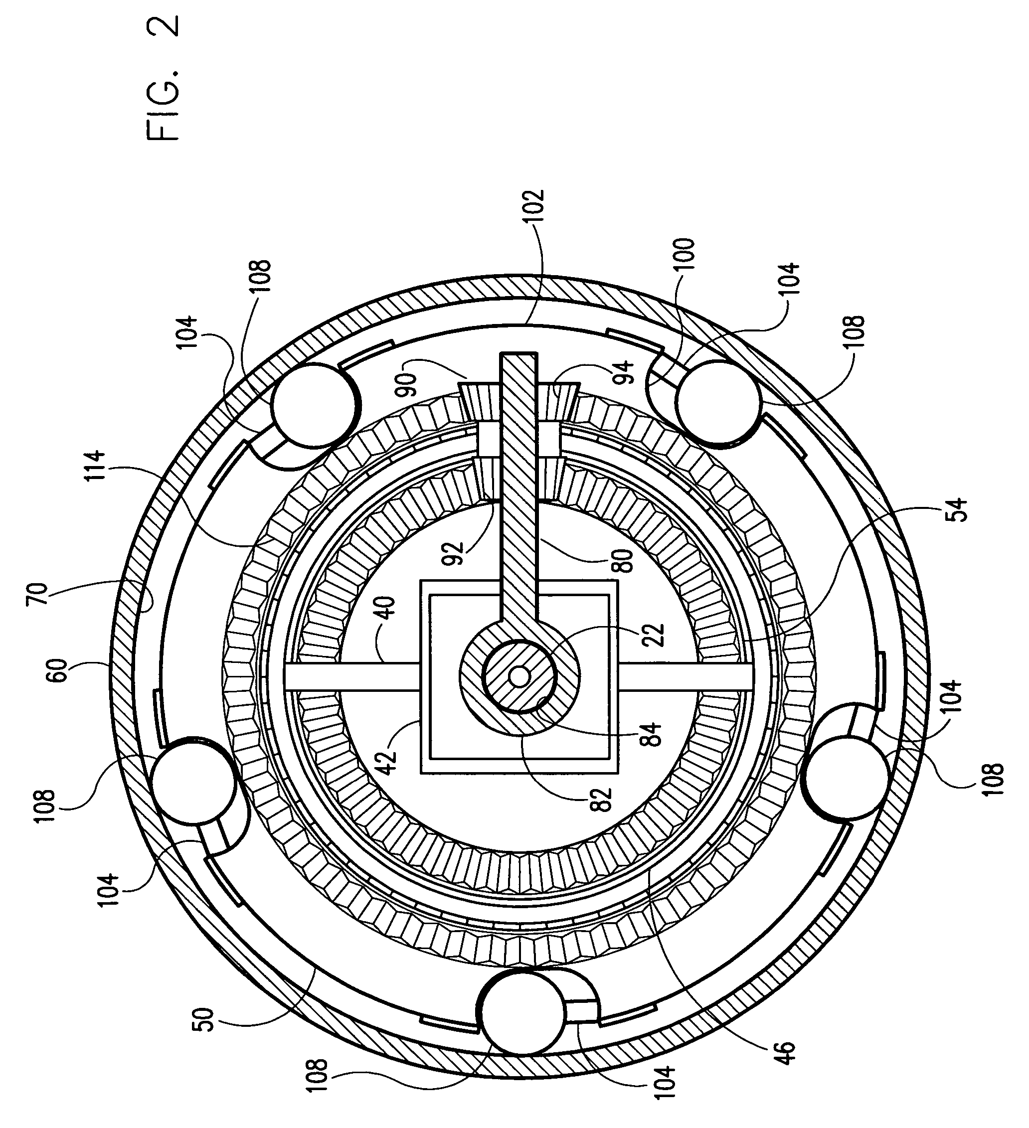
[0016]Referring now to the drawings and in particular to FIG. 1, a variable speed ratio transmission of the present invention is designated in its entirety by the reference numeral 20. The transmission 20 includes a central main axle 22 extending along an imaginary primary axis 24 of the transmission, an input (generally designated by 26) rotatably mounted on the axle by ball bearings 28, and an output (generally designated by 30) rotatably mounted on the main axle and the input by ball bearings 32. As illustrated in FIG. 2, a transverse axle 40 extending laterally with respect to the primary axis 24. The transverse axle 40 includes a yoke 42 at its middle that surrounds the main axle 22. A ball bearing assembly, generally designated by 44, is fixed to the opposite ends of the transverse axle 40. The ball bearing assembly 44 includes an inner race 46 mounted on the transverse axle 40 and an outer race 48 rotatably mounted on the inner race 46 for rotation around the circumference of...


PUM


Abstract

A variable speed ratio transmission including a drive element having a spherical frictional engagement surface centered on a primary axis, a carrier having a roller axle orbiting the primary transmission axis spaced from the spherical surface by a predetermined distance, and a roller rotatably and slidably mounted on the roller axle. The roller axle is angled with respect to a tangent of the spherical engagement surface so the roller tends to slide axially along the roller axle toward the frictional engagement surface to frictionally engage the engagement surface when a relative motion between the drive element and the carrier is in an engaging drive direction and to slide axially along the roller axle away from the frictional engagement surface of the drive element to disengage the engagement surface when the relative motion between the drive element and the carrier is in a disengaging drive direction opposite the engaging direction.

Description

BACKGROUND OF THE INVENTION[0001]The present invention relates generally to a transmission, and more particularly to a variable speed ratio transmission for transmitting rotational motion from an input to an output at an infinite number of speed ratios within a predetermined range of speed ratios.[0002]Transmissions are commonly used to transmit rotational motions from an input to an output at a variety of speed ratios. Although most transmissions are operable at fixed discrete speed ratios, some conventional transmissions are infinitely variable over a range of speed ratios. Such infinitely variable transmissions are operable at any speed ratio between a minimum speed ratio and a maximum speed ratio. However, most of these conventional infinitely variable transmissions do not permit the speed ratio to be changed while the input and the output are standing still. As a result, when the required input torque becomes too great for the power source providing the torque to the input, the...

Claims


Application Information

Patent Timeline
Patent Type & Authority Patents(United States)
IPC IPC(8): F16H1/32
CPCF16H15/50
Inventor FERRAR, PHILIP T.
Owner FERRAR PHILIP T
Features
  • R&D
  • Intellectual Property
  • Life Sciences
  • Materials
  • Tech Scout
  • Unparalleled Data Quality
  • Higher Quality Content
  • 60% Fewer Hallucinations
Learn More