Hydraulic release system with manually operated hydraulic lock valve for spring-applied, hydraulically-released parking brake system

a technology of hydraulic release system and hydraulic lock valve, which is applied in the direction of brake system, brake components, vehicle components, etc., and can solve problems such as problems

Active Publication Date: 2009-10-13
PARKER INTANGIBLES LLC
View PDF7 Cites 10 Cited by
  • Summary
  • Abstract
  • Description
  • Claims
  • Application Information

AI Technical Summary

Problems solved by technology

Obviously, a problem is presented if the parking brakes are in their normal unreleased state.

Method used


Image

  • Hydraulic release system with manually operated hydraulic lock valve for spring-applied, hydraulically-released parking brake system
  • Hydraulic release system with manually operated hydraulic lock valve for spring-applied, hydraulically-released parking brake system
  • Hydraulic release system with manually operated hydraulic lock valve for spring-applied, hydraulically-released parking brake system

Examples


Embodiment Construction

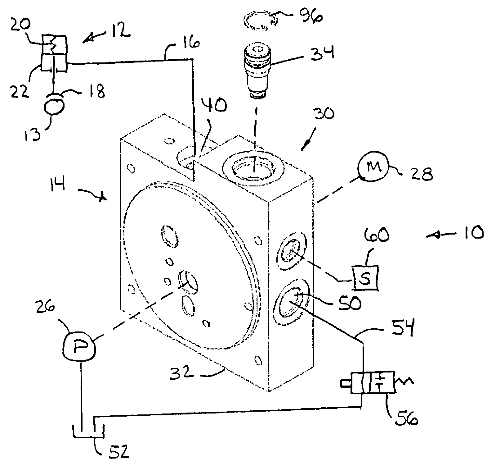
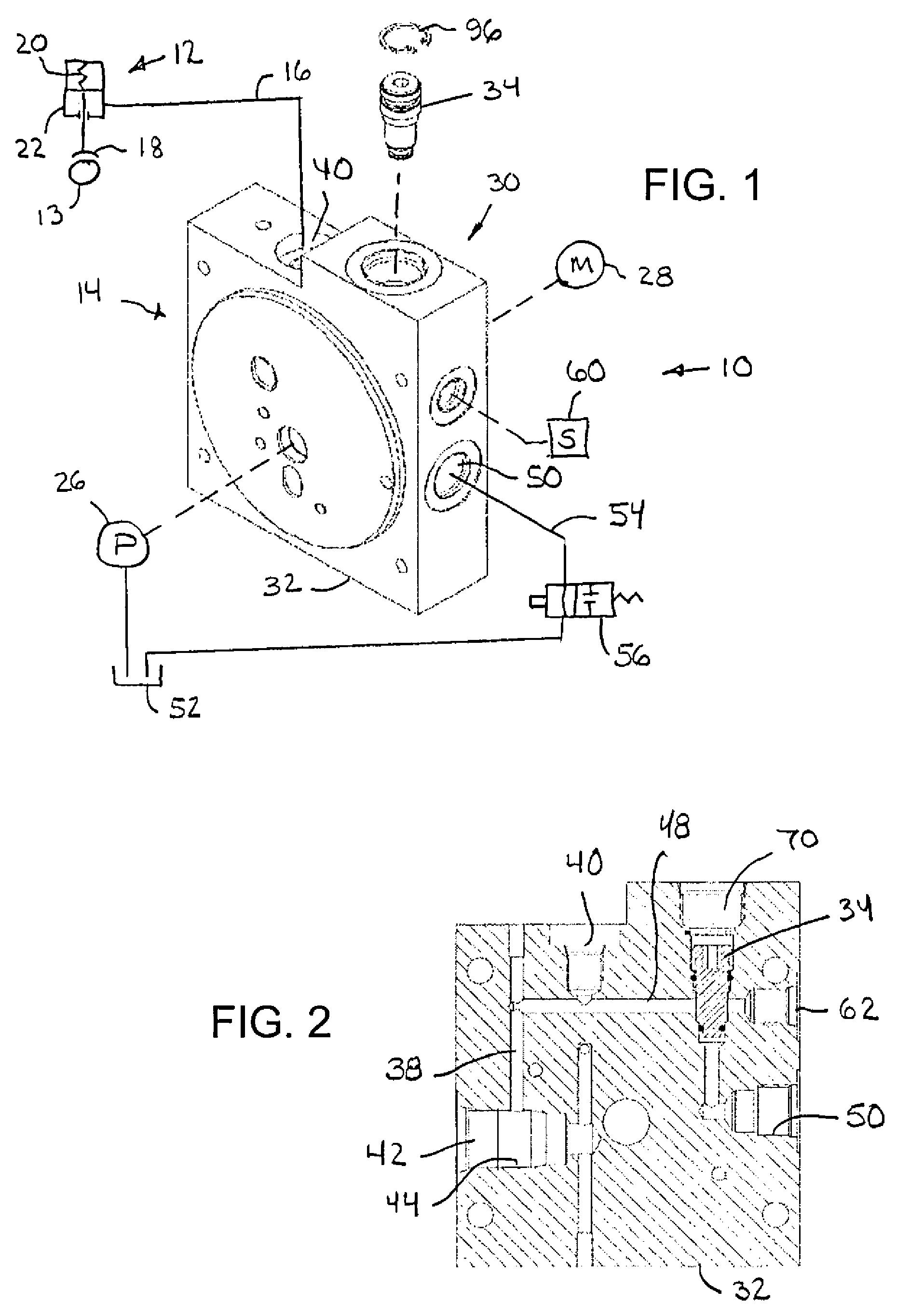
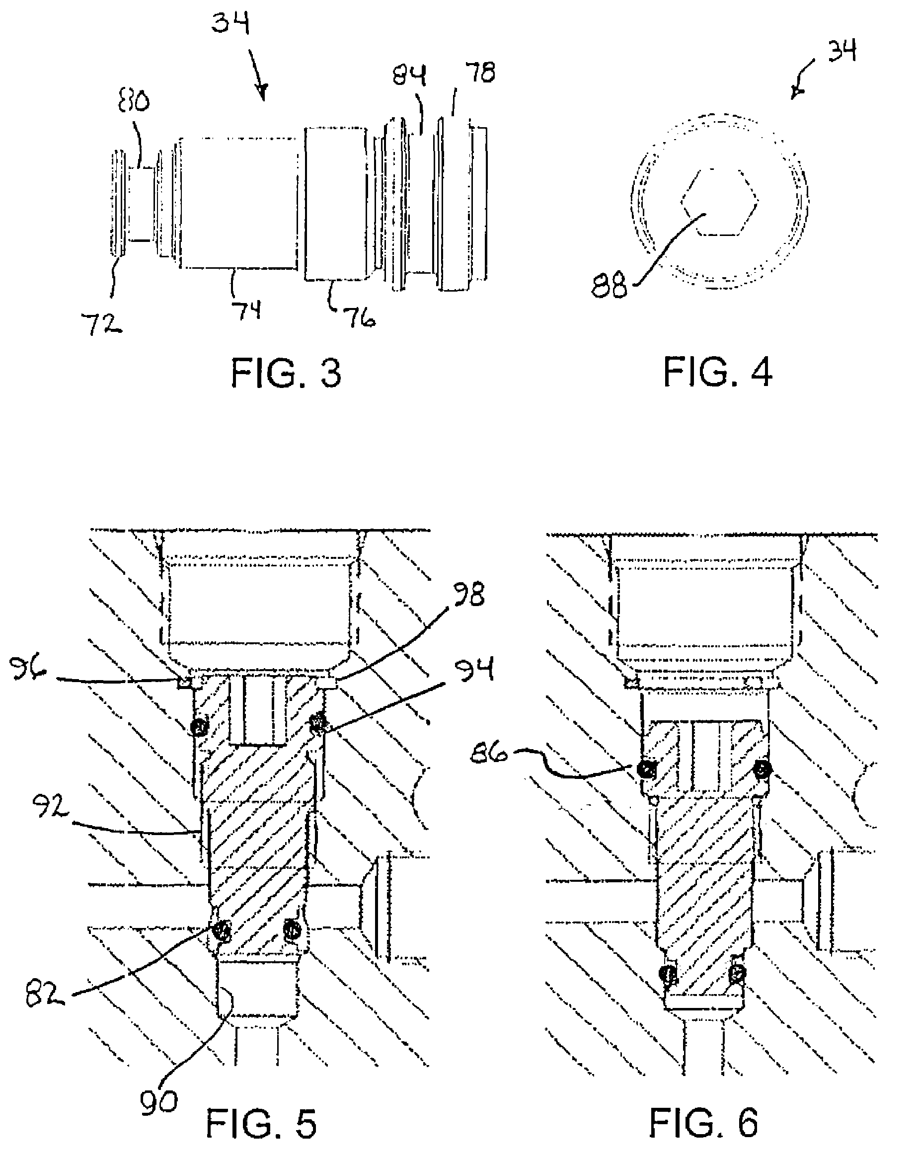
[0016]Referring now in detail to the drawings and initially to FIG. 1, a spring-applied, hydraulically-released (SAHR) parking brake system is indicated generally at 10. The system is intended for use in a vehicle such as a recreational vehicle. The parking brake system 10 generally comprises at least one brake assembly 12 associated with a drive shaft 13 (or wheel(s)) of the vehicle and a hydraulic release system 14 coupled to the brake assembly by a supply conduit 16. The brake assembly 12 includes a brake 18, a spring 20 which biases the brake 18 towards an applied position, and a brake release actuator 22. The hydraulic release system 14 includes a pump 26 (or other source of pressurized hydraulic fluid), a motor 28 for driving the pump 26, and a manifold block assembly 30. The manifold block assembly 30 includes a manifold block (body) 32 and a hydraulic lock valve 34.

[0017]With additional reference to FIG. 2, the manifold block 32 includes an inlet flow passage 38 connecting t...


PUM


Abstract

A hydraulic manifold assembly for use in a hydraulic release system operable to control a spring applied, hydraulically released parking brake assembly, includes a manifold block and a manually operated hydraulic lock valve assembled in the manifold block. The manifold block includes a high pressure inlet port, an actuator port for connection to a brake release actuator, an outlet port for connecting to a hydraulic fluid reservoir, and an internal passage connecting an actuator port to the outlet port. The manually operated lock valve is manually movable between an open position allowing flow of hydraulic fluid from the actuator port to outlet port and a closed position blocking flow of hydraulic fluid from the actuator port to the outlet port, the hydraulic lock valve in its closed position containing pressurized fluid in the actuator to keep the brake released.

Description

[0001]The invention herein described relates generally to vehicles, particularly recreational vehicles (RVs), including spring-applied, hydraulically-released parking brake systems and, more particularly, to a hydraulic release system with a manually operated hydraulic lock valve that can be closed to contain pressurized fluid in the brake release actuator(s) for releasing the parking brake(s) to permit movement of the vehicle during vehicle assembly.BACKGROUND OF THE INVENTION[0002]Many vehicles heretofore have employed spring-applied, hydraulically-released (SAHR) parking brake systems. In these systems, a brake such as shoe assembly or a disk assembly is engaged under the force of a spring which permanently biases the brake towards its applied or engaged position. The brake is released by hydraulic pressure generated by a pump driven directly or indirectly by the vehicle's engine.[0003]SAHR parking brake systems have included brake override assemblies to permit manual brake overr...

Claims


Application Information

Patent Timeline
Patent Type & Authority Patents(United States)
IPC IPC(8): B60T13/74
CPCB60T13/04B60T13/22B60T13/10
Inventor ZIEGLER, DOUGLAS JON
Owner PARKER INTANGIBLES LLC
Why Eureka
Try Eureka