Alignment device for automotive side view mirror

a technology for side view mirrors and alignment devices, which is applied in the direction of mirrors, instruments, mountings, etc., can solve the problems of misalignment of drivers' positions and other problems

Inactive Publication Date: 2009-10-13
BEHBEHANI IRAJ
View PDF13 Cites 11 Cited by
  • Summary
  • Abstract
  • Description
  • Claims
  • Application Information

AI Technical Summary

Benefits of technology

[0006]The curved nature of the mirrors allows lateral compression of images, giving a sense of the lateral separation of an approaching vehicle.

Problems solved by technology

Yet the seating position of a driver can lead to misalignments unless the curved side view mirrors are properly adjusted.

Method used


Image

  • Alignment device for automotive side view mirror
  • Alignment device for automotive side view mirror
  • Alignment device for automotive side view mirror

Examples


Embodiment Construction

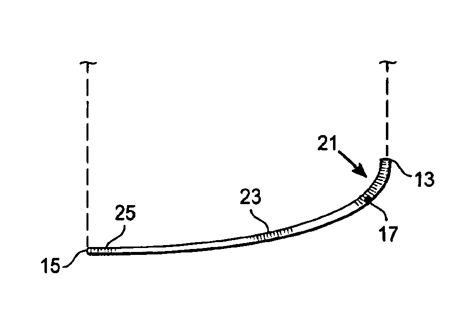
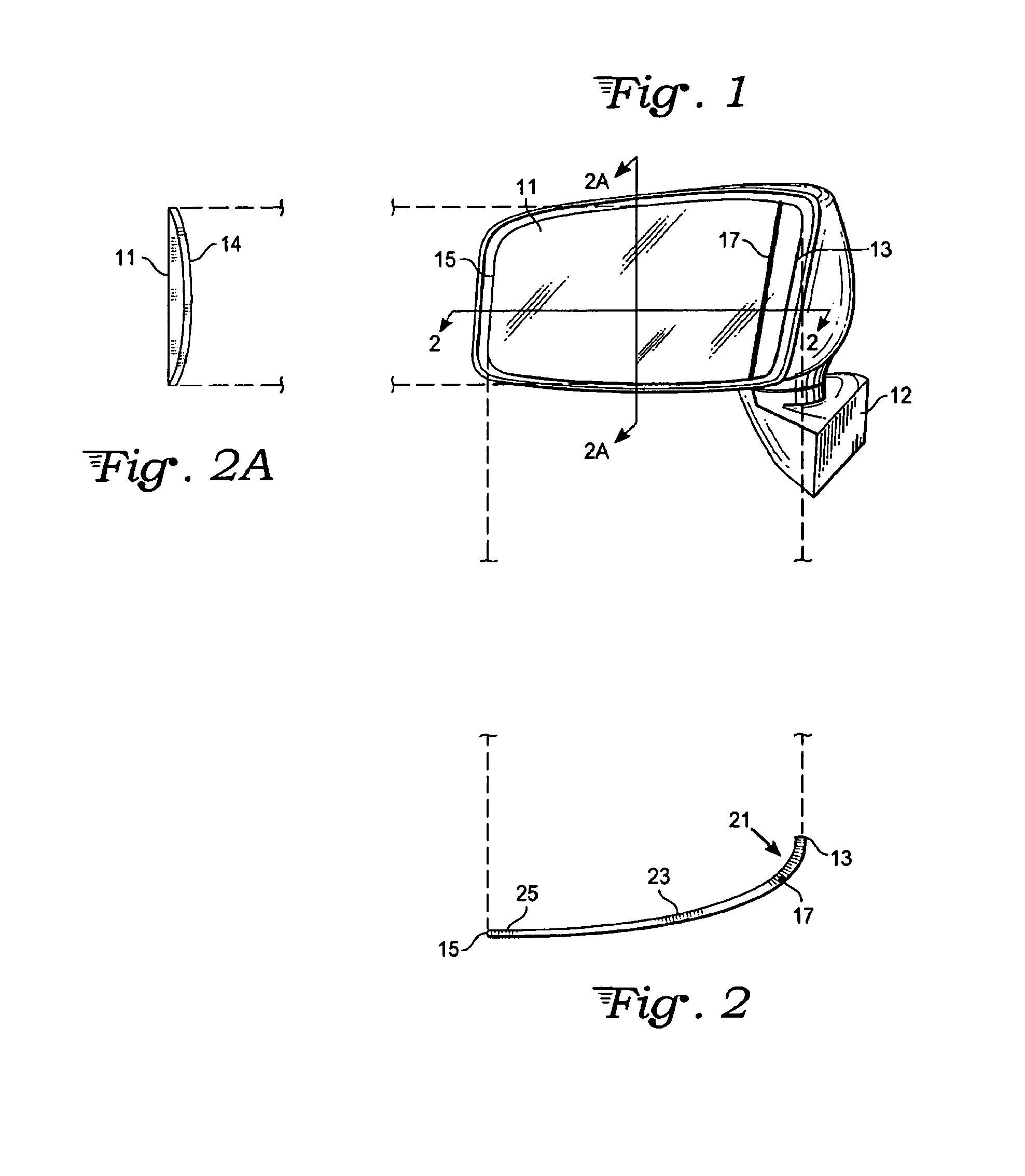
[0021]With reference to FIG. 1 a curved mirror 11 is seen which is a vehicular curved side view mirror mounted on the driver's side of an automotive vehicle with bracket 12. While this invention is described with reference to automotive vehicles, the invention could be used with trucks, off-road vehicles and other vehicles, but has greatest applicability for use with vehicles that drive on highways with traffic overtaking the subject vehicle from the sides. A similar mirror of the present invention is mounted on the passenger side of the vehicle with added curvature near the passenger position, as described below with reference to FIG. 4.

[0022]The mirror 11 has an inward edge 13 which is closest to the vehicle and an outward edge 15 which is distal to the vehicle. The mirror features a scribe line 17, preferably but not necessarily straight, that is within three-fourths of an inch of the inward edge 13 and preferably within one-fourth of an inch, with a typical placement of the scri...


PUM


Abstract

An alignment system for side view mirrors featuring a mirror with regions of diverse curvature, with an upright alignment line in a region of greater curvature. The side view mirror is set up so that the side of a user's vehicle lies entirely on the side of the alignment line closest to the vehicle. This generates a cone of vision to the rear of the vehicle which overlaps with the cone of vision from a rear view mirror such that blind spots are greatly reduced or eliminated.

Description

TECHNICAL FIELD.[0001]The invention relates to automotive safety devices and, more particularly, to automotive side view mirrors.BACKGROUND ART[0002]Since the invention of the automobile, there has been concern with the rear view available to a driver by means of mirrors. Various combinations of side view and rear view mirrors have been devised, with particular concern to a blind spot which exists in certain angular sections behind a vehicle. To minimize the blind spot, wide angle side view mirrors have been devised, particularly curved mirrors. It is known that parabolic mirrors, with variable curvature, can be particularly effective in reducing or eliminating blind spots thereby giving a driver a wide angle view of optics behind the vehicle.[0003]Exemplary curved, or curved and planar, side view mirrors can be found in the U.S. Pat. Nos. 4,331,382; 5,793,542; 5,096,291, as well as in published applications 2003 / 0039039 and 2004 / 0114260. All of the curved or curved-planar mirrors s...

Claims


Application Information

Patent Timeline
Patent Type & Authority Patents(United States)
IPC IPC(8): G02B5/10
CPCB60R1/08G02B7/182G02B5/10
Inventor BEHBEHANI, IRAJ
Owner BEHBEHANI IRAJ
Why Eureka
Try Eureka