System and method for reducing discontinuity of gray level in an image buffer memory

a gray level and image buffer technology, applied in the field of image buffer memory, can solve the problems of reducing the efficiency of the entire system, adding processing time, and drams as image buffers can only have some specified capacities, and achieve the effect of reducing the discontinuity of gray level

Inactive Publication Date: 2009-11-10
SUNPLUS TECH CO LTD
View PDF4 Cites 0 Cited by
  • Summary
  • Abstract
  • Description
  • Claims
  • Application Information

AI Technical Summary

Benefits of technology

[0006]The object of the present invention is to provide a system and method for reducing discontinuity of gray level in an image buffer memory, which can save required image buffer memory and overcome the prior problem of discontinuity of gray level on image at horizontal direction.
[0007]In accordance with one aspect of the present invention, there is provided a method for reducing discontinuity of gray level in an image buffer memory, which reduces N bits to (N−k) bits for each pixel on an input image (N and k are positive integers and N>k), so as to save required memory and reduce discontinuity of gray level. The input image includes a plurality of pixels in a matrix. The method includes the steps of: selecting a plurality of interleaved pixels from the input image; adding a specific value of 2k−1 in the pixels selected; and deleting lower k bits for each pixel of the input image.
[0008]In accordance with another aspect of the present invention, there is provided a system for reducing discontinuity of gray level in an image buffer memory, which reduces N bits to (N−k) bits for each pixel on an input image so as to save required memory (N and k are positive integers and N>k). The input image includes a plurality of pixels in a matrix. The system includes: a pixel selecting means for selecting a plurality of interleaved pixels from the input image; an adder for adding a specific value of 2k−1 in the pixels selected; and a pixel bit deleting means for deleting lower k bits for each pixel of the input image.

Problems solved by technology

However, with current DRAM standards, DRAMs as image buffers can only have some specified capacities.
However, a conventional approach for further compression only processes a half frame of motion picture at a time, thereby adding processing time and reducing entire system efficiency.

Method used


Image

  • System and method for reducing discontinuity of gray level in an image buffer memory
  • System and method for reducing discontinuity of gray level in an image buffer memory
  • System and method for reducing discontinuity of gray level in an image buffer memory

Examples


Embodiment Construction

[0014]To better understanding, preferred embodiments are described in detail in the following.

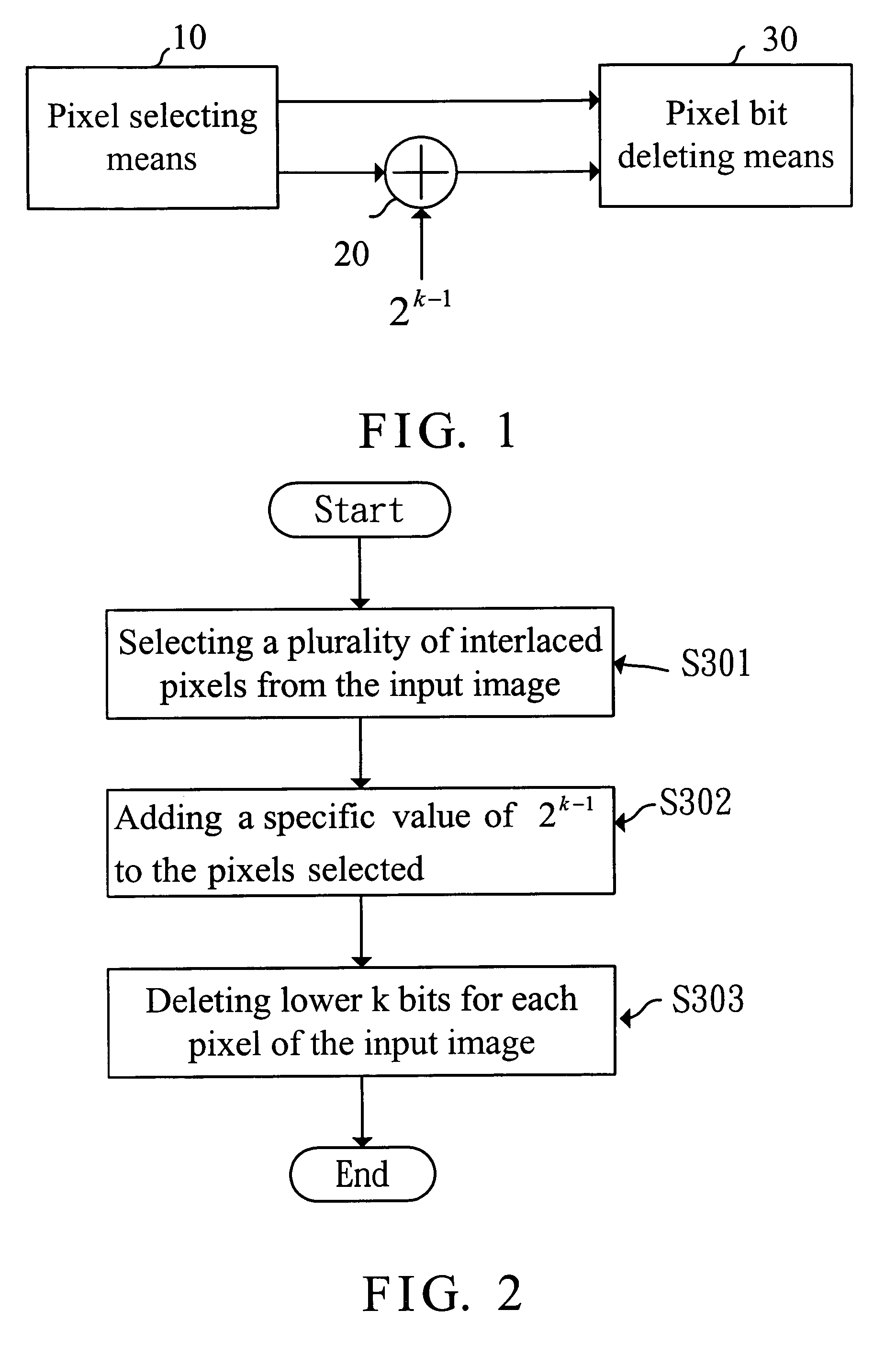
[0015]FIG. 1 is a block diagram of a system for reducing discontinuity of gray level in an image buffer memory in accordance with the invention. In FIG. 1, the system is provided to reduce N bit to (N−k) bits for each pixel on an input image so as to save required memory (N and k are positive integers and N>k), which includes a pixel selecting means 10, an adder 20 and a pixel bit deleting means 30. As shown, the pixel selecting means 10 selects a plurality of interleaved pixels from the input image. The adder 20 adds a specific value of 2k−1 to the pixels selected by the pixels selecting means. The pixel bit deleting means 30 deletes lower k bits for each pixel of the input image.

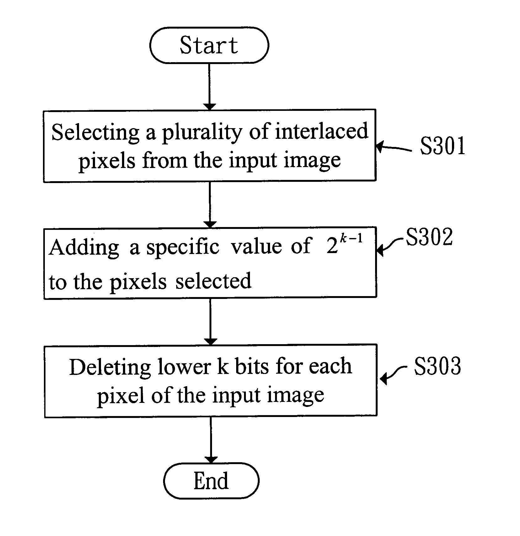
[0016]FIG. 2 is a flowchart of a method applied for reducing discontinuity of gray level in an image buffer memory in accordance with the invention. As shown in FIG. 2, the method can reduce N bit to (N−k) bits fo...


PUM


Abstract

A system and method for reducing discontinuity of gray level in an image buffer memory is provided, which reduces N bits to (N−k) bits for each pixel on an input image, so as to save required memory and reduce discontinuity of gray level. The input image includes a plurality of pixels in a matrix. The method includes the steps of: selecting a plurality of interleaved pixels from the input image; adding a specific value of 2k−1 in the pixels selected; and deleting lower k bits for each pixel of the input image.

Description

BACKGROUND OF THE INVENTION[0001]1. Field of the Invention[0002]The present invention relates to the technical field of image buffer memory and, more particularly, to a system and method for reducing discontinuity of gray level in an image buffer memory.[0003]2. Description of Related Art[0004]Image compression and decompression is widely used in video and multimedia applications. In accordance with certain similarity between two adjacent frames of consecutive pictures, image compression can highly increase efficiency of data compression. This is achieved by using motion estimation to omit data where current frame is similar to the nearest preceding frame, and only recording the different ones. Such a compression method is also referred to as a frame-related compression. Image compression is performed in a unit of GOP (group of picture) consisting of three types of I, B and P frames. In general, a GOP has 15 frames: an I-frame at the first position, a P-frame at the second position,...

Claims


Application Information

Patent Timeline
Patent Type & Authority Patents(United States)
IPC IPC(8): G06K9/36H04N1/387H04N7/26
CPCH04N19/90H04N19/86
Inventor CHEN, WEN-KUAN
Owner SUNPLUS TECH CO LTD
Why Eureka
Try Eureka