Method, computer software code, and system for determining a train direction at a railroad crossing

a technology of railway crossing and train direction, applied in the field of railway transportation, can solve the problems of not taking into account the direction of the train, the system is unreliable and expensive, and the motorist is not provided constant warning

Active Publication Date: 2009-11-17
GENERAL ELECTRIC CO
View PDF8 Cites 13 Cited by
  • Summary
  • Abstract
  • Description
  • Claims
  • Application Information

AI Technical Summary

Problems solved by technology

Such systems do not take into account train direction.
However, these systems have proven unreliable and expensive.
Furthermore, they have proven not to provide constant warning to motorist.
New crossing monitoring systems are being developed to automatically record and document the performance of crossing warning devices as trains pass by, but these new systems do not readily lend themselves to determining a direction that a passing train is traveling.
Thus, such new systems still require an additional element to be able to determine a direction a train is traveling.
Railroad owners and / or users of railroads spend a significant amount of time and money adhering to Federal Railroad Administration (FRA) mandated testing of crossing warning systems.
Performing these tests amounts to a significant amount of time and money, especially considering the number of active crossings that currently exist.
A solution is therefore needed for determining a direction a vehicle is traveling on a railway track as it approaches a road crossing so that the significant amount of time and money spent by Railroad owners and / or users of railroads adhering to requirements, such as those mandated by the FRA, to test crossing warning systems is limited.

Method used


Image

  • Method, computer software code, and system for determining a train direction at a railroad crossing
  • Method, computer software code, and system for determining a train direction at a railroad crossing
  • Method, computer software code, and system for determining a train direction at a railroad crossing

Examples


Embodiment Construction

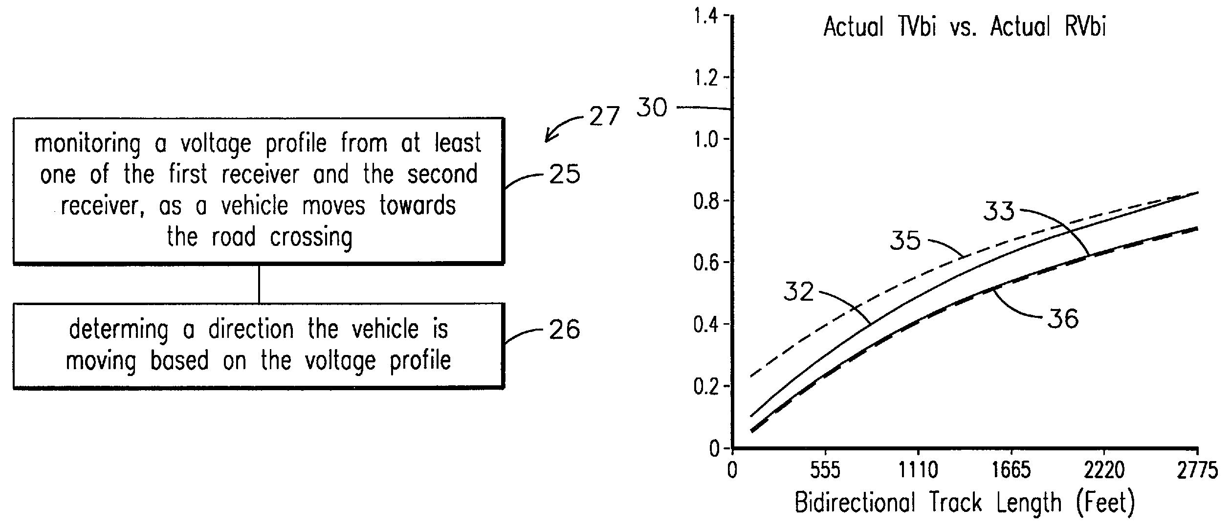
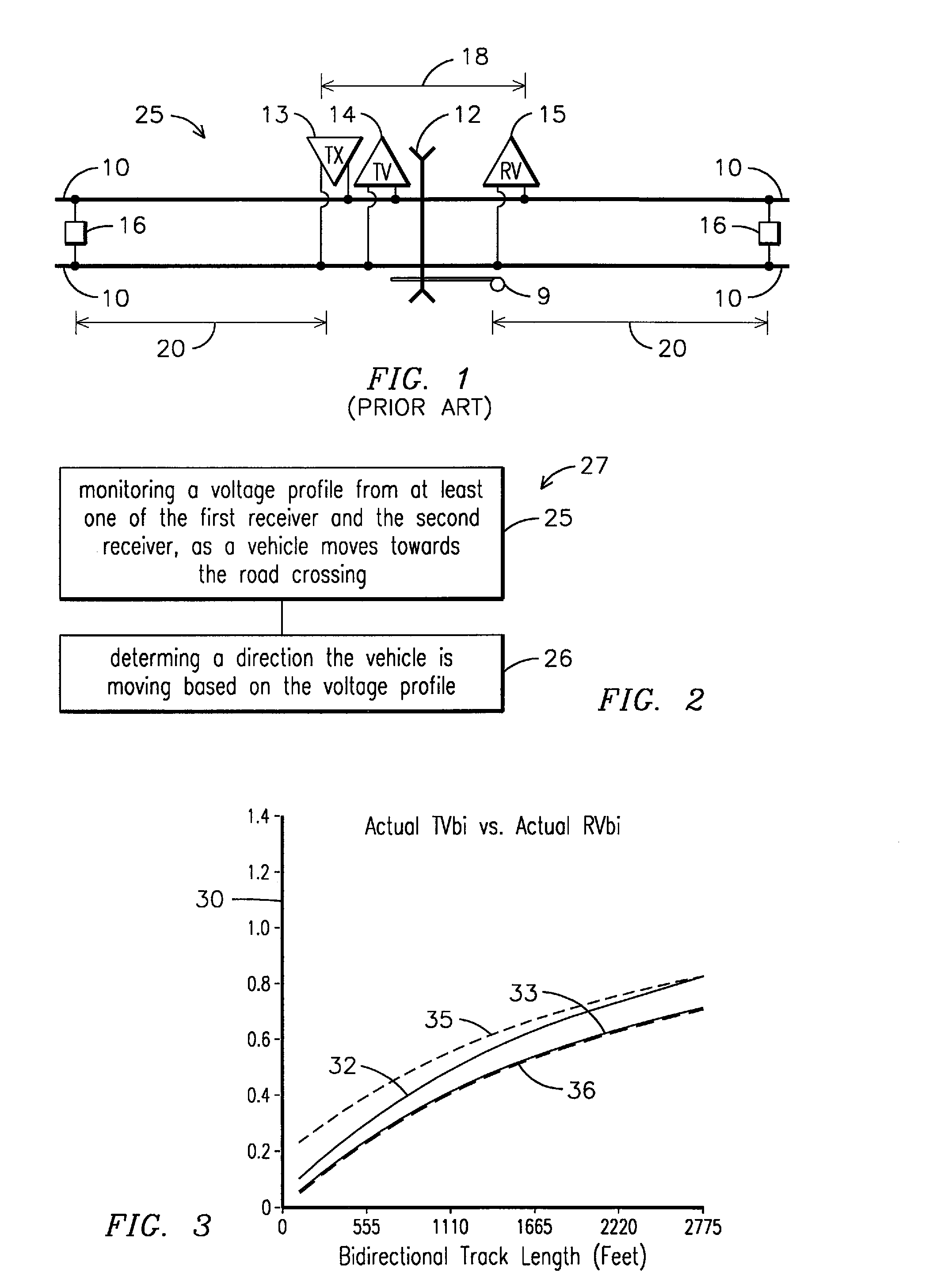
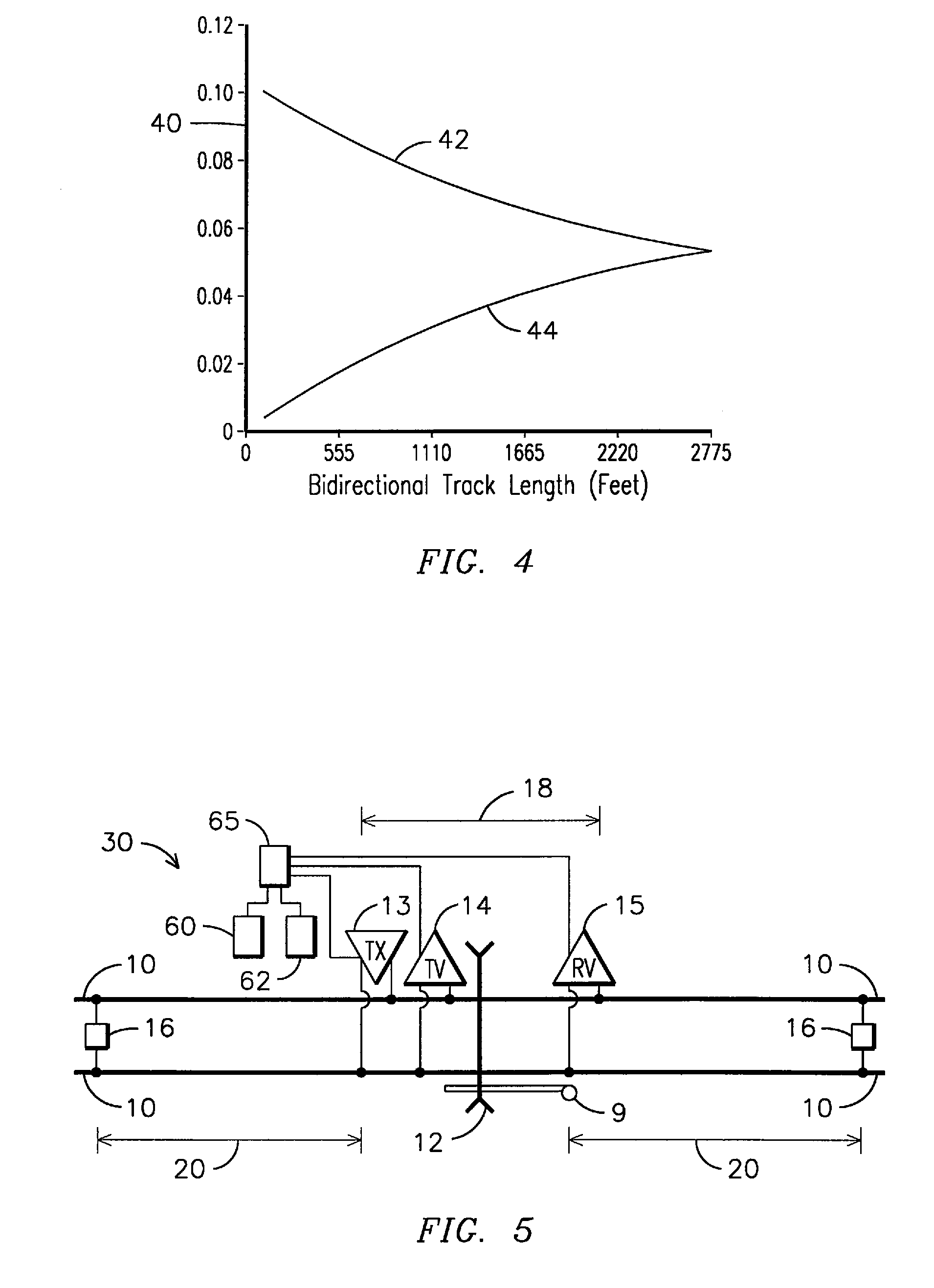
[0020]Reference will now be made in detail to the embodiments consistent with the invention, examples of which are illustrated in the accompanying drawings. Wherever possible, the same reference numerals used throughout the drawings refer to the same or like parts. Though this invention is described with respect to rail vehicles, such as but not limited to trains and / or railway maintenance vehicles, those skilled in the art will readily recognize that the present invention may also be used for other vehicle systems, such as, but not limited to, where vehicles move over a given surface and other surfaces used where other vehicles, such as but not limited to non-rail vehicles, move along another surface that intersect with and / or bisects the first given surface.

[0021]Embodiments of the present invention solve the problems in the prior art by providing a system, method, and computer implemented method, such as but not limited to a computer software code, for determining a direction a t...


PUM


Abstract

In a railroad crossing warning system having an electronic transmitter located on a first side of a road crossing connected across both railway rails, a first electronic receiver on the first side of the road crossing connected across both railway rails, a second electronic receiver on the second side of the road crossing connected across both railway rails, a method for determining direction a vehicle is traveling, the method including monitoring a voltage profile from at least one of the first receiver and the second receiver, as a vehicle moves along the railway rails towards the road crossing, and determining a direction the vehicle is moving based on the voltage profile.

Description

FIELD OF INVENTION[0001]This field of invention relates to rail transportation and, more specifically, to a method, computer software code, and a system for determining a direction a vehicle is traveling on a railway track.BACKGROUND OF THE INVENTION[0002]Fixed rail transportation systems, that include one or more rail vehicles traveling over spaced apart rails of a railway track, have been an efficient way of moving cargo and people from one geographical location to another. In densely populated countries and countries having unimproved road transportation systems, rail vehicles may be the primary means for moving people and cargo. Additionally, rail transportation is used in areas where little to no population exists. Accordingly, there are probably millions of miles of railroad track throughout the world that need to be maintained. Because road transportation is also prevalent, roads are known to bisect, and or cross, railway tracks. Typically, a crossing warning system is locate...

Claims


Application Information

Patent Timeline
Patent Type & Authority Patents(United States)
IPC IPC(8): B61L1/00
CPCB61L29/286B61L1/181
Inventor FRIES, JEFFREY M.
Owner GENERAL ELECTRIC CO
Why Eureka
Try Eureka