Compact head up display with wide viewing angle

a head-up display and wide viewing angle technology, applied in the field of display systems, can solve the problems of narrow viewing angles, low contrast of images, high cost, etc., and achieve the effect of wide viewing angles, thin and undesiredly high curved conventional combiners, and low cos

Active Publication Date: 2009-11-17
ROCKWELL COLLINS INC
View PDF15 Cites 42 Cited by
  • Summary
  • Abstract
  • Description
  • Claims
  • Application Information

AI Technical Summary

Problems solved by technology

Although HUDs are useful in a variety of applications, there are several problems with conventional HUDs, among which high cost, narrow viewing angles, mechanical constraints, and low contrast of images are of particular concern.
Moreover, conventional combiners are either undesirably thick and heavy for most applications, or are thin and undesirably highly curved.
Thin combiners thus typically do not provide the necessary undistorted view of the background scene, especially when the combiner is thick enough to be adequately durable.

Method used


Image

  • Compact head up display with wide viewing angle
  • Compact head up display with wide viewing angle
  • Compact head up display with wide viewing angle

Examples


Embodiment Construction

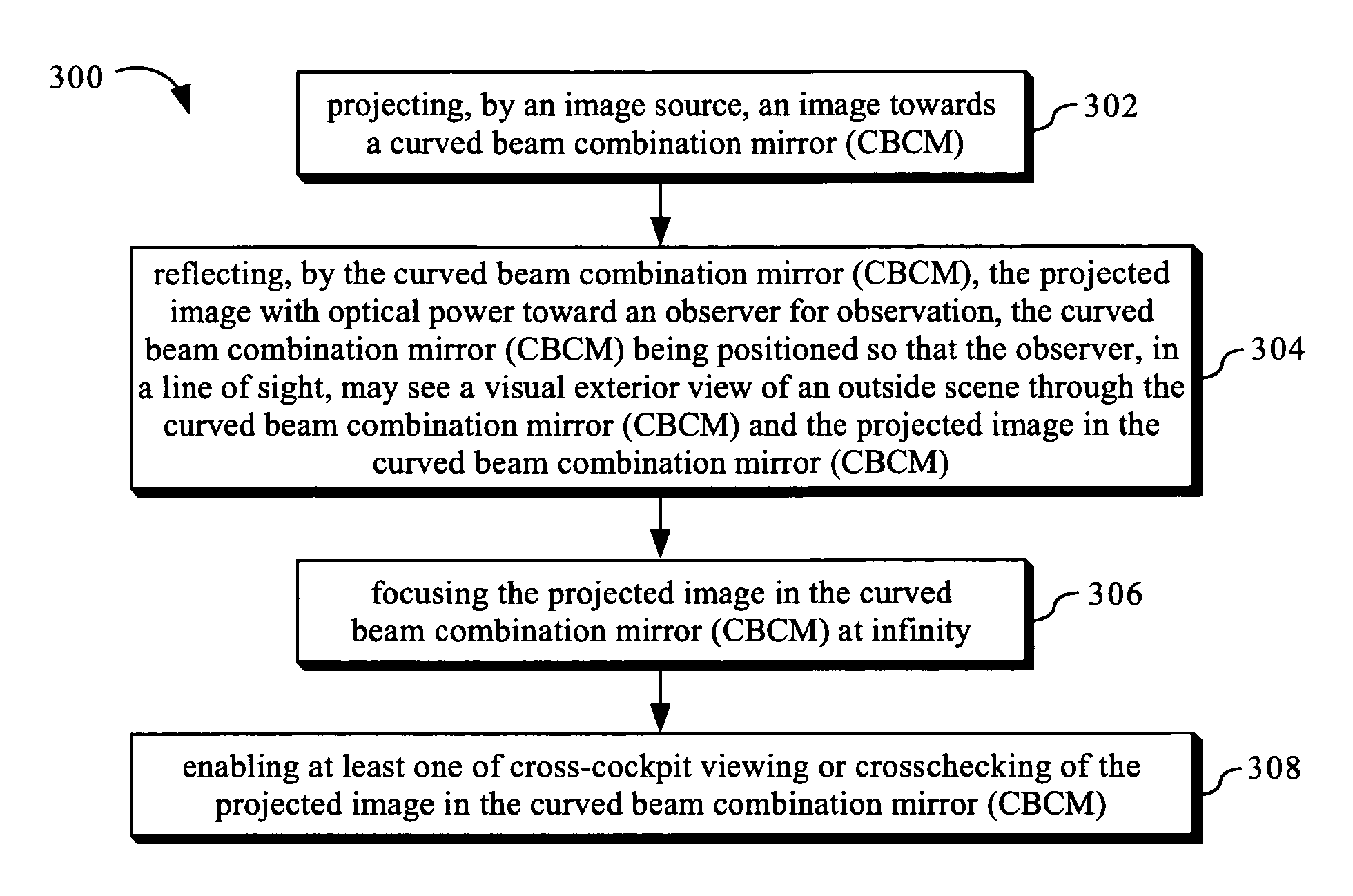
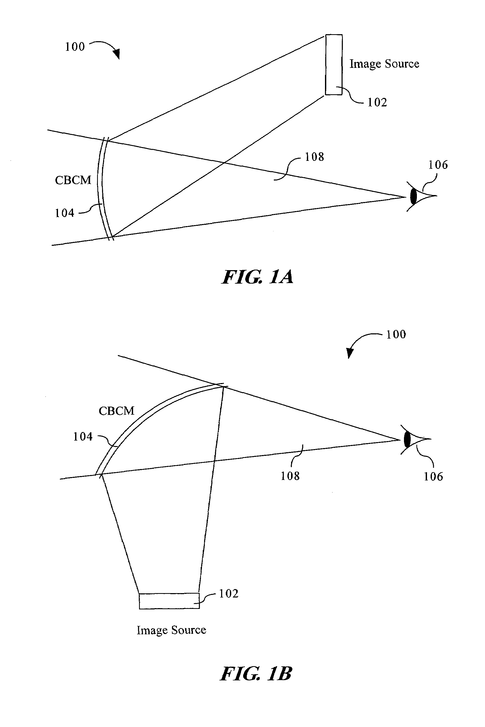
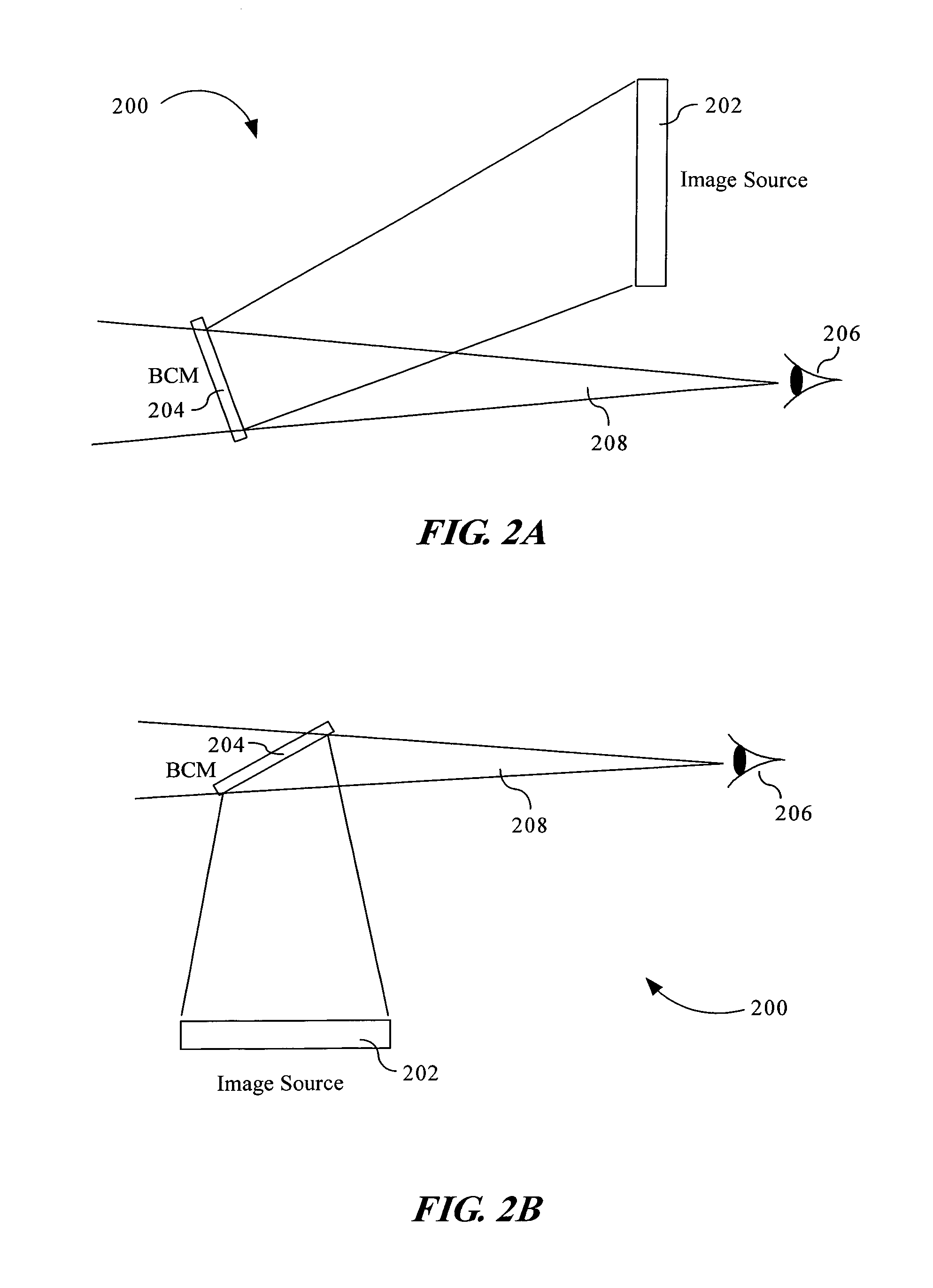
[0015]Reference will now be made in detail to the presently preferred embodiments of the invention, examples of which are illustrated in the accompanying drawings.

[0016]In an exemplary aspect, the present invention may utilize a flat panel LCD as an image source and a beam combination mirror (BCM) or curved beam combination mirror (CBCM) as a combiner. Conventional combiners are either undesirably thick and heavy for most applications, or are thin and undesirably highly curved. The thick combiners often contain a pair of cooperative lens elements, at least one of which includes an embedded spherical surface coated with a spectrally reflecting thin film. The external surfaces of these thick combiners are flat so as to provide an undistorted view of the background scene. Thin combiners, on the other hand, typically employ a pair of spherical external surfaces, one of which carries the spectrally reflecting thin film. Thin combiners thus typically do not provide the necessary undistort...


PUM


Abstract

The present invention provides an optical display system and method for producing images and presenting the images for observation in combination with an observer's visual exterior view of an outside scene. The optical display system may include an image source for projecting an image, and a curved beam combination mirror (CBCM) or beam combination mirror (BCM) for reflecting the projected image toward an observer for observation. The image source may be a transmissive LCD, a reflective LCD, a digital micromirror device, a laser display, or the like. The CBCM or BCM may be positioned so that the observer, in a line of sight, may see a visual exterior view of an outside scene through the CBCM or BCM and the projected image in the CBCM or BCM.

Description

FIELD OF THE INVENTION[0001]The present invention generally relates to the field of display systems, particularly to a method and optical display system for producing images and presenting the images for observation in combination with an observer's visual exterior view of an outside scene.BACKGROUND OF THE INVENTION[0002]A Head-Up Display (HUD) is a means of projecting information directly into a human's visual field. The HUD was pioneered for military aviation and has since been used in other applications. HUDs are typically used in aircraft to provide pilots with information superimposed onto their forward field of view through the aircraft windshield. The information displayed may be data or symbolic images indicative of flight conditions such as the operating condition of the aircraft, environmental information or guidance information for use in directing the aircraft to its destination. These images are presented in overlying fashion on the pilot's field of view so as not to i...

Claims


Application Information

Patent Timeline
Patent Type & Authority Patents(United States)
IPC IPC(8): G02B27/14G09G5/00
CPCG02B27/0101G02B2027/011G02B2027/0123G02B2027/0118G02B2027/0114
Inventor PENG, GUOLINSTEFFENSMEIER, MARTIN J.
Owner ROCKWELL COLLINS INC
Why Eureka
Try Eureka