Re-circulating paper accumulator

a paper accumulator and accumulator technology, applied in the field of sheet accumulators, can solve the problems of reducing the size of the mail piece creation device, the size of the paper sheet that is to be handled, and the time staff, so as to reduce the overall size of the device, reduce the overall volume, and increase the degree of design freedom

Inactive Publication Date: 2009-11-24
PITNEY BOWES LMITED
View PDF2 Cites 0 Cited by
  • Summary
  • Abstract
  • Description
  • Claims
  • Application Information

AI Technical Summary

Benefits of technology

[0030]Embodiments of the invention provide a sheet accumulator configuration that is adaptable to a suitable shape so as to fit conveniently within a sheet handling apparatus into which the accumulator is to be installed. More particularly, the sheet accumulator is not constrained to the use of a circulation path that is circular in cross-section. The sheet circulation path can thus be shaped appropriately, either to reduce the overall volume occupied by the sheet accumulator or to beneficially adapt the shape of the circulation path so as to fit in between and around adjacent components within the sheet handling apparatus into which the sheet accumulator is to be installed. This provides the designer of a paper handling apparatus incorporating such a sheet accumulator with a greater degree of design freedom for incorporating the sheet circulation path into the device, and can advantageously allow the overall size of such a device to be reduced.

Problems solved by technology

These systems are large complex, and typically require a full-time staff of specially trained operators in order to oversee production.
One of the limiting factors in reducing the size of such mail piece creation devices is the size of the sheets of paper that are to be handled.
However, the driving force must not be so great that it will either damage the sheet being driven, or cause one or both of the adjacent sheets to become buckled unintentionally.
Shingling of the stack occurs when these frictional forces are overcome, causing the adjacent sheets to separate and become staggered.
On the other hand, unintentional buckling of paper sheets can lead to either misalignment or creasing of the sheets, which would be undesirable.

Method used


Image

  • Re-circulating paper accumulator
  • Re-circulating paper accumulator
  • Re-circulating paper accumulator

Examples


Embodiment Construction

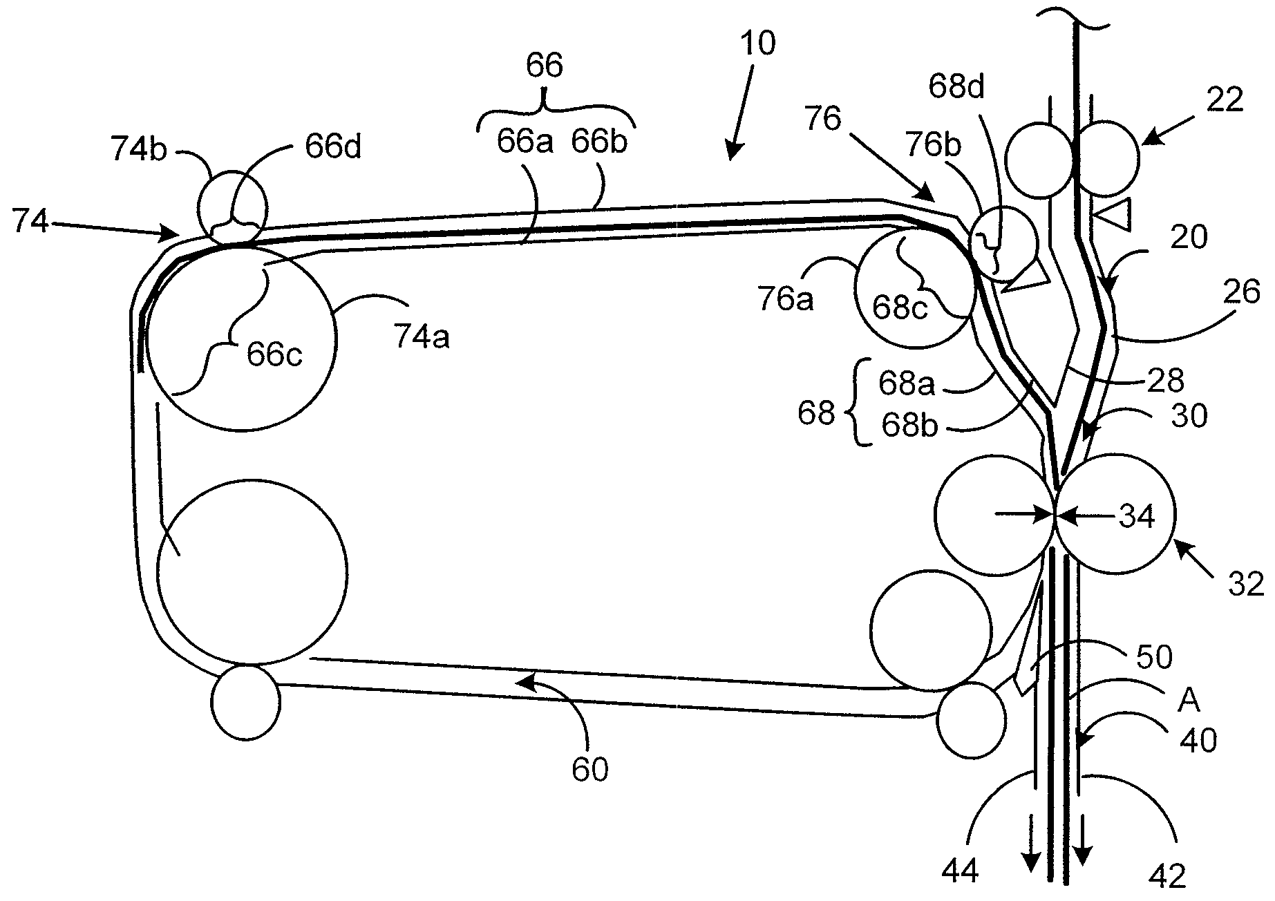
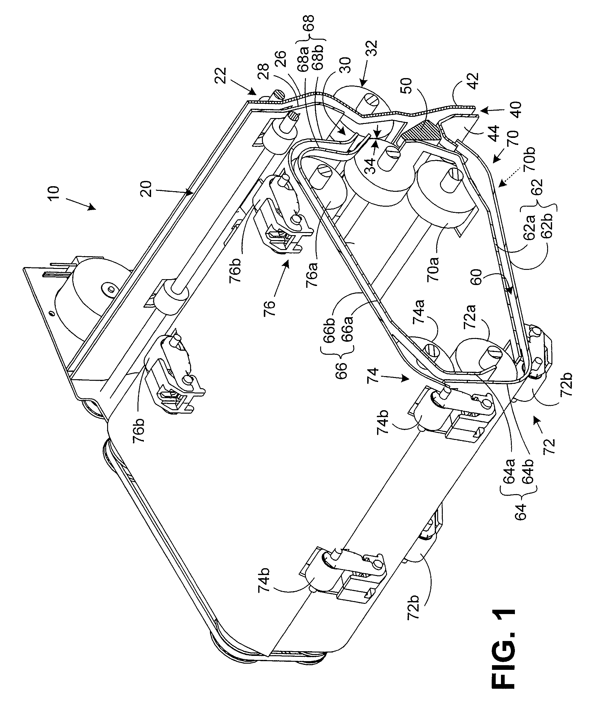
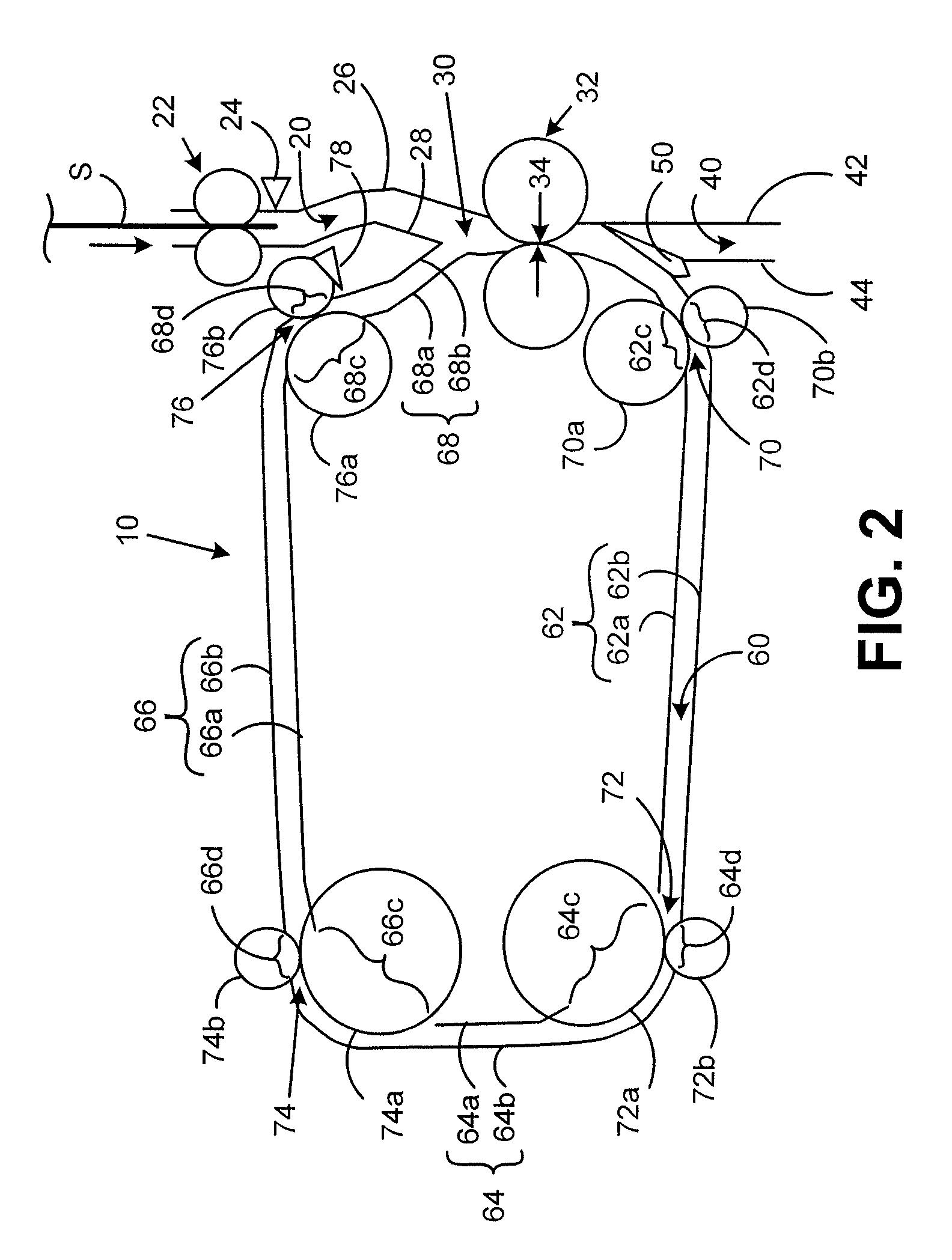
[0051]FIG. 1 is a three-dimensional view of a re-circulating accumulator, showing the main paper-handling components of the device.

[0052]The re-circulating accumulator 10 includes an inlet feed path 20, along which sheets, in particular sheets of paper, are fed into the re-circulating accumulator 10 to an accumulation location 30. The inlet feed path 20 is provided with an inlet roller pair 22. The inlet roller pair 22 may be driven, for feeding sheets along the inlet feed path, or may be configured as a pair of stopping rollers, for arresting sheets immediately prior to their entry into the re-circulating accumulator 10. This allows the entry of sheets along inlet feed path 20 to be timed in accordance with the desired mode of operation of the re-circulating accumulator 10. Of course, the inlet roller pair 22 may be a driven roller pair for feeding sheets as well as being able to provide the function of arresting sheets on entry into the re-circulating accumulator 10. As shown in F...


PUM

PropertyMeasurementUnit
sizeaaaaaaaaaa
sizesaaaaaaaaaa
timeaaaaaaaaaa

Abstract

There is disclosed a sheet re-circulating accumulator (10) comprising: an inlet feed path (20) to an accumulation location (30); an outlet feed path (40); a sheet circulation path (60) defined by stationary sheet guide means (62, 64, 66, 68); and sheet driving means (32, 70, 72, 74, 76) associated with the sheet circulation path (60) for selectively advancing a partial accumulation (P) of one or more sheets (S) at the accumulation location (30) around the sheet circulation path (60), so that the partial accumulation (P) is guided by the stationary sheet guide means (62, 64, 66, 68) at the leading edge of the partial accumulation (P) while being driven, and back to the accumulation location (30) to accumulate the next sheet (S) fed from the inlet feed path (20) with the partial accumulation (P), and delivering an accumulation (A) of sheets (S) along said outlet feed path (40).

Description

CROSS REFERENCE TO RELATED APPLICATIONS[0001]This application claims the benefit of the filling date of Nov. 30, 2006, for United Kingdom application number 0623968.5, which is owned by the assignee of the present application.FIELD OF THE INVENTION[0002]The present invention relates to a sheet accumulator. Such a sheet accumulator is suitable for use in a sheet handling apparatus, and finds particular application in a paper handling apparatus, such as a mail piece creation device.BACKGROUND[0003]Many types of paper handling apparatus are known, for manipulating sheets of paper by performing a sequential series of process steps on individual sheets. Such process steps involve transporting, printing, collating, accumulating, folding, etc. In many cases, it is desirable to process a number of individual sheets so as to group a plurality of such sheets together into an ordered bundle. The process of placing such sheets in order is known as collating, while the process of grouping the pl...

Claims


Application Information

Patent Timeline
Patent Type & Authority Patents(United States)
IPC IPC(8): B65H33/04
CPCB65H29/58B65H39/10B65H2301/4454B65H2301/4213
Inventor FARMER, GEOFFREY A.
Owner PITNEY BOWES LMITED
Why Eureka
Try Eureka