Linear synchronous motor

Inactive Publication Date: 2011-06-30
SANYO DENKI CO LTD
View PDF5 Cites 1 Cited by
  • Summary
  • Abstract
  • Description
  • Claims
  • Application Information

AI Technical Summary

Benefits of technology

[0016]Alternatively, the first and second direct drive shafts and the first and second guide shafts may be disposed such that a virtual plane including an axial line of the first direct drive shaft and an axial line of the second direct drive shaft crosses a virtual plane including an axial line of the first guide shaft and an axial line of the second guide shaft in a region surrounded by the first and second direct drive shafts and the first and second guide shafts. With this arrangement, it may also be possible to reduce dimensions of the linear synchronous motor in a direction where the first and second direct drive shafts are disposed and dimensions of the linear synchronous motor in a direction where the first and second guide shafts are disposed.
[0017]Preferably, a spring mechanism is provided between one of the first and second connecting members and the stator core unit. The spring mechanism is configured to generate a biasing force for biasing the one of the first and second connecting members in a direction apart from the stator core unit when the one of the first and second connecting members approaches the stator core unit. Assume that the linear synchronous motor is used such that axes of

Problems solved by technology

Further, a magnetic circuit between the cores is not closed, so that magnetic flux leakage tends to occur.
For that reason, e

Method used


Image

  • Linear synchronous motor
  • Linear synchronous motor
  • Linear synchronous motor

Examples


Embodiment Construction

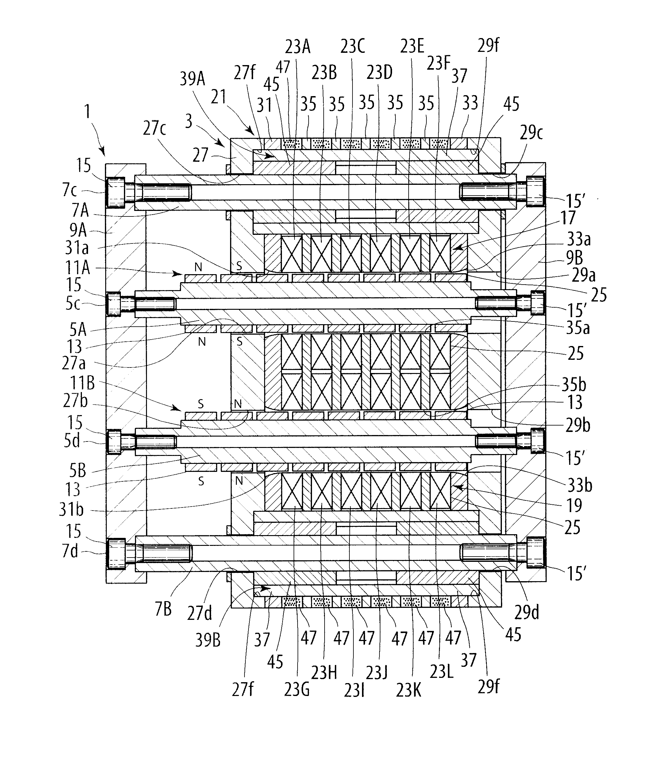
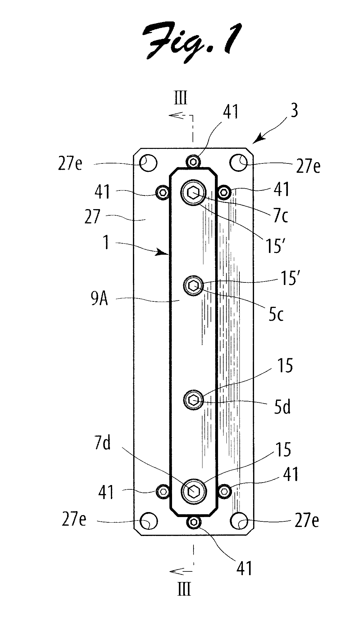
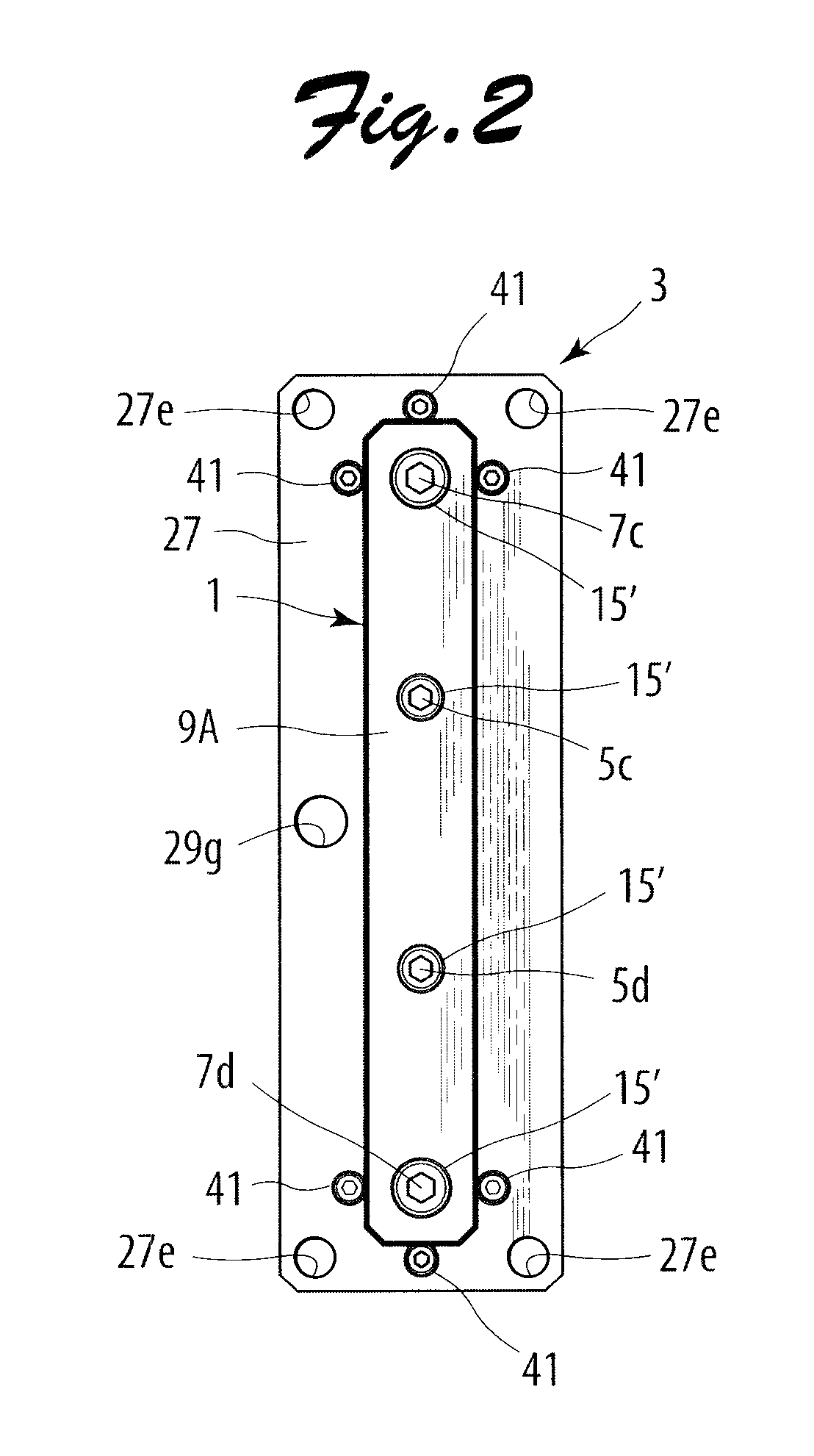
[0038]Examples of embodiments of the present invention will be described below in detail. FIGS. 1 and 2 are respectively a front view and a rear view of a linear synchronous motor in an embodiment of the present invention. FIG. 3 is a sectional view taken along line III-III in FIG. 1. The linear synchronous motor in this embodiment includes a mover 1 and a stator 3, as shown in FIG. 3. The mover 1 includes a first direct drive shaft 5A and a second direct drive shaft 5B, a first guide shaft 7A and a second guide shaft 7B, and a first connecting member 9A and a second connecting member 9B. Each of the first and second direct drive shafts 5A and 5E is made of a magnetic conductive material, has an elongate cylindrical shape, and reciprocates in an axial direction thereof. A first array of permanent magnets 11A is arranged on an outer peripheral surface of the first direct drive shaft 5A, while a second array of permanent magnets 11B is arranged on an outer peripheral surface of the se...


PUM


Abstract

A stator core unit of a linear synchronous motor is divided into a plurality of divided cores. The divided cores each include a pair of connected portions. The pairs of connected portions are disposed along a first direct drive shaft and a second direct drive shaft to form a pair of connected portion arrays. A yoke is constituted from a pair of yoke elements which are formed of a magnetic conductive material and magnetically connect the connected portions of the pair of connected portion arrays. A first array of permanent magnets and a second array of permanent magnets are disposed to be shifted from each other by an electrical angle of 180°. A first array of windings and a second array of windings are excited with the first and second arrays of windings being shifted by an electrical angle of 180°.

Description

TECHNICAL FIELD[0001]The present invention relates to a linear synchronous motor in which a mover linearly moves relative to a stator.BACKGROUND ART[0002]Japanese Patent Application Publication No. 2001-286122 (JP2001-286122A) discloses a linear synchronous motor comprising a stator and a mover that linearly moves relative to the stator. The mover includes a direct drive shaft configured to reciprocate in an axial direction and an array of permanent magnets including a plurality of permanent magnets fixed to the direct drive shaft. The stator includes a plurality of windings and a stator core unit having slots formed therein for receiving the plurality of annular windings. The annular windings are each formed of an annularly wound winding conductor and are disposed so as to surround the direct drive shaft. The stator core unit is constituted from a plurality of stator core divided bodies assembled with each other in the axial direction. The stator core divided bodies are formed by c...

Claims


Application Information

Patent Timeline
IPC IPC(8): H02K41/03H02P25/06
CPCH02K1/14H02K1/18H02K1/28H02K1/2726H02K16/00H02K41/031H02K7/08H02K16/02H02K2213/12
Inventor TANG, YUQISUGITA, SATOSHI
Owner SANYO DENKI CO LTD
Why Eureka
Try Eureka