
Enhanced shape characterization device and method

a technology of shape and characterization device, applied in the field of shape determination, can solve the problems of difficult field calibration using known methods, devices without axial shapes,

Active Publication Date: 2009-11-24
STRYKER EURO OPERATIONS HLDG LLC
View PDF175 Cites 23 Cited by
  • Summary
  • Abstract
  • Description
  • Claims
  • Application Information

AI Technical Summary

Problems solved by technology

With space at a premium in a surgical suite, this can be a problem.
Lastly, some devices do not have an axial shape with the result that these bodies have been difficult to field calibrate using known methods.

Method used


Image

  • Enhanced shape characterization device and method
  • Enhanced shape characterization device and method
  • Enhanced shape characterization device and method

Examples


Embodiment Construction

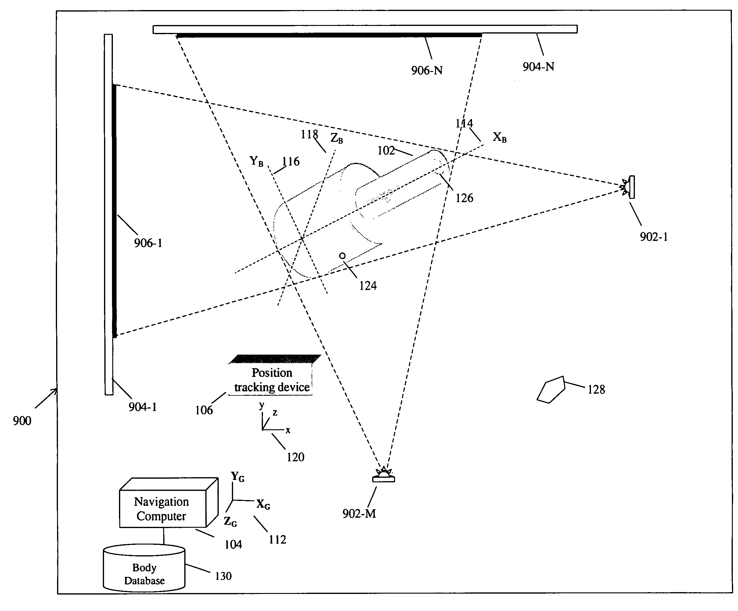
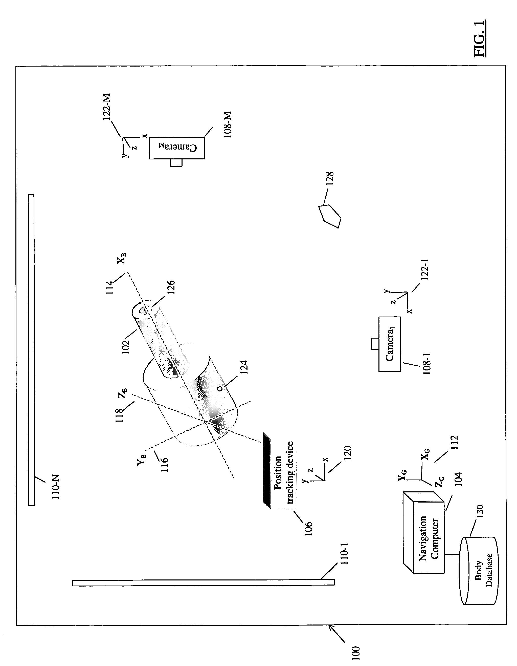
[0031]FIG. 1 shows one embodiment of a shape characterization system 100 useful to characterize a body 102, that includes a navigation computer 104, a position tracking device 106, a plurality of cameras 108-1 through 108-M, and a plurality of backgrounds 110-1 through 110-N. The shape characterization system 100 locates the position and orientation of the body 102 in space with respect to a global coordinate system 112 established by the navigation computer 104. Specifically, the shape characterization system determines the position and orientation of body axes XB 114, YB 116, and ZB 118 that are local to the body 102 with respect to the global coordinate system 112 established by the navigation computer 104. The position and orientation of the body axes 114, 116, and 118 determined by the shape characterization system 100 can be expressed as a linear transformation matrix that maps points on the body 102 in the local coordinate space defined by the body axes 114, 116, and 118 to p...


PUM


Abstract

The shape and orientation of rigid or nearly rigid moveable bodies are determined using a shape characterization. Sensors capture a plurality of representations of different perspectives of the body that are analyzed to determine a bounding volume of the body. The shape of the body is determined from the bounding volume. The position of the body is determined using tracking devices that sense the position of the body. The bounding volume and position information are combined to define the shape and orientation in space of the body, and in particular the position of a point of interest on the body.

Description

CROSS REFERENCE TO RELATED APPLICATIONS[0001]Not applicableREFERENCE REGARDING FEDERALLY SPONSORED RESEARCH OR DEVELOPMENT[0002]Not applicableSEQUENTIAL LISTING[0003]Not applicableBACKGROUND OF THE INVENTION[0004]1. Field of the Invention[0005]This invention relates to the determination of the shape of rigid or nearly rigid bodies. More particularly, this invention relates to shape determination of such bodies using a computer navigation system.[0006]2. Description of the Background of the Invention[0007]Computer determination of the location of bodies has been used in manufacturing and medical fields for a number of years. Computer navigation requires that the bodies to be tracked by the navigation system have a known shape, so that the orientation and position of the bodies can be properly tracked by the system. Tracking is accomplished by either attaching a tracking device to the body or embedding the tracking device into the body. There are numerous tracking technologies includi...

Claims


Application Information

Patent Timeline
Patent Type & Authority Patents(United States)
IPC IPC(8): G01B11/14A61B5/00G06F19/00G06K9/00
CPCG01S5/163G01B11/245
Inventor MOCTEZUMA DE LA BARRERA, JOSE LUISSCHULZ, WALDEAN A.MALACKOWSKI, DONALD W.
Owner STRYKER EURO OPERATIONS HLDG LLC
Learn More