Drive transmitting mechanism and image forming apparatus

a transmission mechanism and drive technology, applied in the direction of electrographic process apparatus, yielding coupling, instruments, etc., can solve the problems of color misalignment on printed sheets, vibration caused by these driven components, and the position adjustment of the driving shaft with respect to the drum shaft is extremely difficult to achieve, so as to minimize the change in the rotational speed of the driven shaft, facilitate coupling and decoupling, and smooth transmission of rotation

Active Publication Date: 2009-11-24
KK TOSHIBA +1
View PDF7 Cites 61 Cited by
  • Summary
  • Abstract
  • Description
  • Claims
  • Application Information

AI Technical Summary

Benefits of technology

[0013]A drive transmitting mechanism according to the present invention comprises: a driving shaft; a driven shaft which is rotated as the driving shaft rotates; and a pair of coupling members that are attached to the driving shaft and the driven shaft, respectively, to transmit a rotational drive force from the driving shaft to the driven shaft. These members oscillate in one diametrical direction and slide at mutually contacting surfaces in another diametrical direction intersecting at right angles to the one diametrical direction. Thus, these members suppress the rotational speed change of the driven shaft, which results from the de-centering and declination between the driving shaft and the driven shaft.
[0016]In the drive transmitting mechanism described above, the de-centering and declination between the driving shaft and the driven shaft can be compensated for (absorbed), achieving smooth transmission of rotation. This can minimize changes in the rotational speed of the driven shaft. This drive transmitting mechanism may be applied to rotate the photosensitive drums provided in a color image forming apparatus of electro-photography type. Then, the apparatus can form clear images without color shifts. The coupling members attached to the driving and driven shafts, respectively, can be easily coupled and decoupled. Therefore, if the drive transmitting mechanism is applied to rotate a photosensitive drum, it will facilitate the setting and removal of the photosensitive drum in and from the housing of the image forming apparatus.

Problems solved by technology

This rotational speed change results in color misalignment on the printed sheets.
This method is disadvantageous, however, in that the position adjustment of the driving shaft with respect to the shaft of the drum is extremely difficult to achieve.
Hence, even if the driving shaft is precisely positioned with respect to the rotating shaft of the drum, it is anticipated that the vibration caused by these driven components generate the misalignment between the rotating shaft and the driving shaft as time passes, due to.
The Oldam coupling can indeed compensate for (absorb) the de-centering, but cannot compensate for the declination.
In this driving-force transmitting device, however, only one of the shafts responds to de-centering and declination.
A large load is inevitably applied to that part of the coupling to which this shaft is attached.
The load is so large that the coupling may be deformed or may be broken.

Method used


Image

  • Drive transmitting mechanism and image forming apparatus
  • Drive transmitting mechanism and image forming apparatus
  • Drive transmitting mechanism and image forming apparatus

Examples


Embodiment Construction

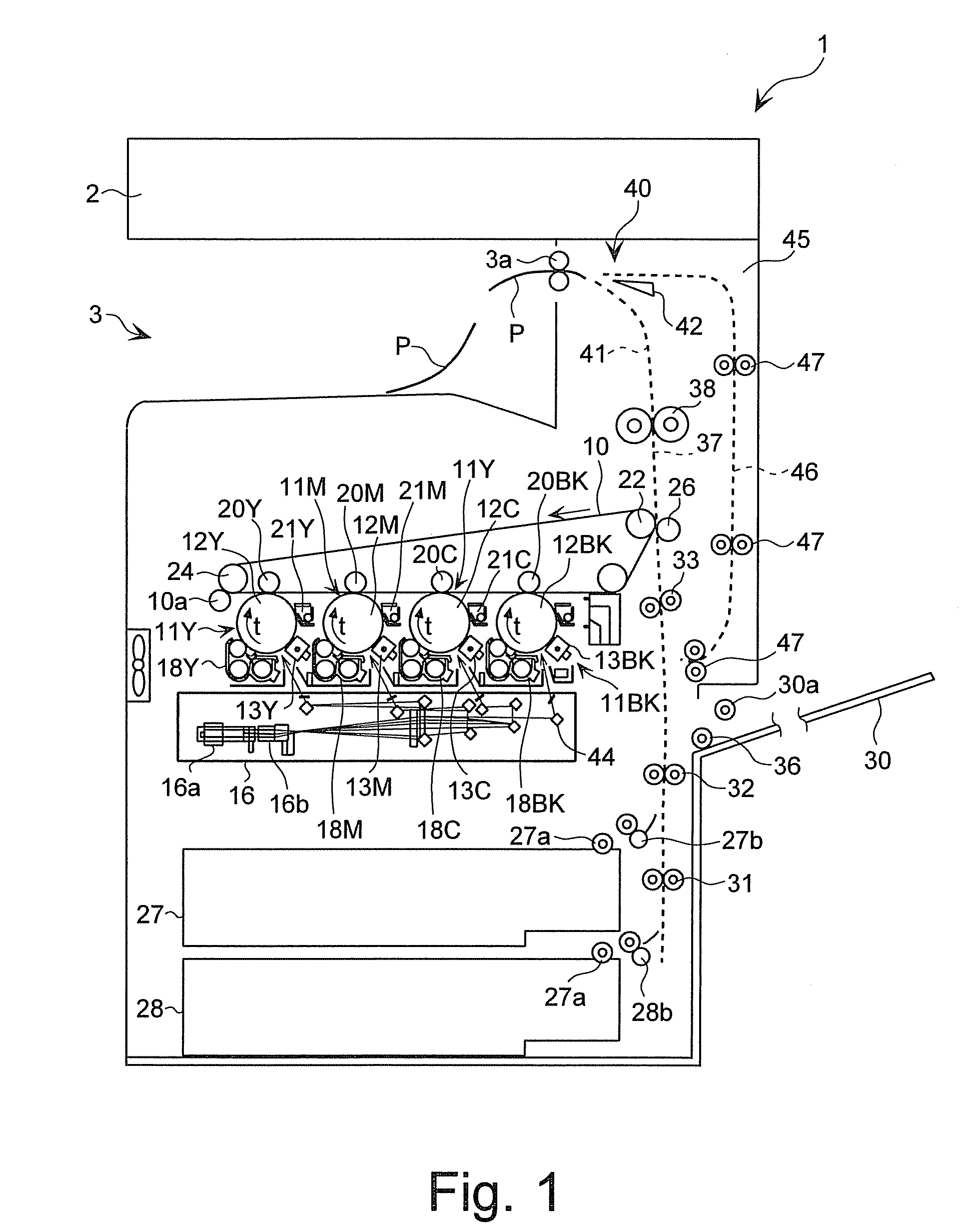
[0027]Embodiments of the present invention will be described in detail, with reference to the accompanying drawings. A color copier of quadruple-tandem type is a type of image forming apparatus according to this invention. The configuration of a drive transmitting mechanism according to this invention, used in the color copier to drive the photosensitive drum will be described.

[0028]FIG. 1 schematically shows the configuration of this color copier 1 of quadruple-tandem type. The color copier 1 comprises a scanner unit 2 provided at the top and a sheet-ejecting unit 3 provided in the housing. The color copier 1 further comprises an intermediate transfer belt 10, a driving roller 22, driven rollers 23 and 24, and four image-forming units 11Y, 11M, 11C and 11BK. The intermediate transfer belt 10 is an intermediate transfer media. The driving roller 22 and the driven rollers 23 and 24 cooperate to stretch and drive the intermediate transfer belt 10. The image-forming units 11Y, 11M, 11C...


PUM


Abstract

A drive transmitting mechanism configured to rotate the photosensitive drum of a color copier has a driving shaft, a driven shaft, and first and second coupling members. The first coupling member has a projection extending in a diametrical direction. The first coupling member is attached to the driving shaft, with amount of freedom to oscillate in a direction intersecting at right angles to the lengthwise direction of the projection. The second coupling member has a recess in which the projection is fitted. The second coupling member is attached to the driven shaft, with amount of freedom to oscillate in the lengthwise direction of the recess. The first and second coupling members oscillate in the diametrical direction and slide on the contacting surface in a diametrical direction intersecting at right angles to the diametrical direction, thus suppressing the rotational speed change of the driven shaft, which results from the de-centering and declination between the driving shaft and the driven shaft.

Description

CROSS REFERENCE TO RELATED APPLICATION[0001]This application is based upon and claims the benefit of priority from prior Japanese Patent Application No. 2006-42776 filed on Feb. 20, 2006, the entire contents of which are incorporated herein by reference.BACKGROUND OF THE INVENTION[0002]1. Field of the Invention[0003]The present invention relates to a drive transmitting mechanism in which a driving shaft and a driven shaft are arranged in a axial alignment and can be coupled and decoupled, and a rotational drive force is transmitted from the driving shaft to the driven shaft via a pair of coupling members, and to an image forming apparatus that comprises this drive transmitting mechanism.[0004]2. Description of the Related Art[0005]In laser printers and digital copiers, which are designed to print high-quality images, the change in the rotational speed of the photosensitive drum greatly influences the image quality. Therefore, the structure of the drive coupling unit for rotating the...

Claims


Application Information

Patent Timeline
Patent Type & Authority Patents(United States)
IPC IPC(8): G03G15/00
CPCF16D3/04G03G15/757G03G2221/1657
Inventor SATO, YOJI
Owner KK TOSHIBA
Why Eureka
Try Eureka