Cargo vehicle with drag reduction

a cargo vehicle and drag reduction technology, applied in the field of trucking industry, can solve the problems of high fuel consumption, complicated and expensive components, and many existing designs, and achieve the effect of avoiding complicated and expensive structures and avoiding interference with truck docking platform operations

Inactive Publication Date: 2009-12-01
FITZGERALD JAMES P
View PDF36 Cites 45 Cited by
  • Summary
  • Abstract
  • Description
  • Claims
  • Application Information

AI Technical Summary

Benefits of technology

[0008]In view of the foregoing, it is an object of the present invention to provide an improved drag-reducing design for the rearward end of semi-trailers and other cargo vehicles that overcomes various drawbacks of existing designs. The present invention achieves this objective by providing a cargo vehicle enclosure with left and right rearward corner portions having built-in air deflectors. The left and right rearward corner portions define left and right air passageways that gradually redirect air flowing rearwardly alongside the left and right sidewalls toward a region of low pressure behind the rearward end portion of the enclosure, while avoiding complicated and expensive structure, avoiding interference with truck docking platform operations, requiring no assembly by the vehicle driver, and fitting within the size limitations of various laws and regulations.
[0014]Thus, the invention provides a cargo vehicle enclosure that directs air toward a region of low pressure behind the rearward end portion of the enclosure while avoiding complicated and expensive structure, avoiding interference with truck docking platform operations, requiring no assembly by the vehicle driver, and fitting within the size limitations of various laws and regulations.

Problems solved by technology

The low-pressure region results in drag and a corresponding higher rate of fuel consumption.
Many existing designs, however, have certain drawbacks.
Others involve complicated and expensive components.
And yet other designs add components that extend laterally beyond maximum width limitations set by laws and regulations, while those that fit within such maximum width limitations are often too restricted in size to function satisfactorily.

Method used


Image

  • Cargo vehicle with drag reduction
  • Cargo vehicle with drag reduction
  • Cargo vehicle with drag reduction

Examples


Embodiment Construction

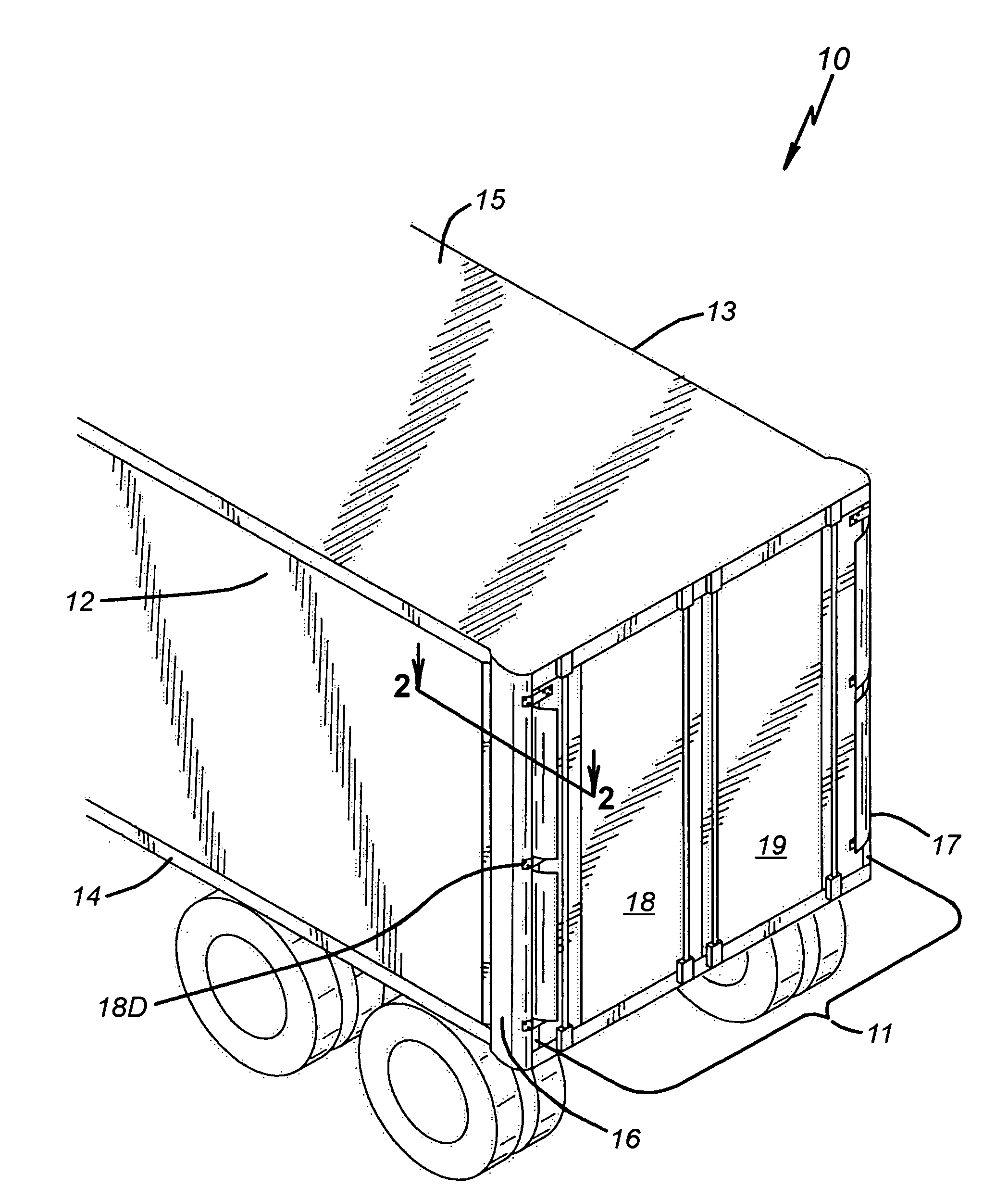
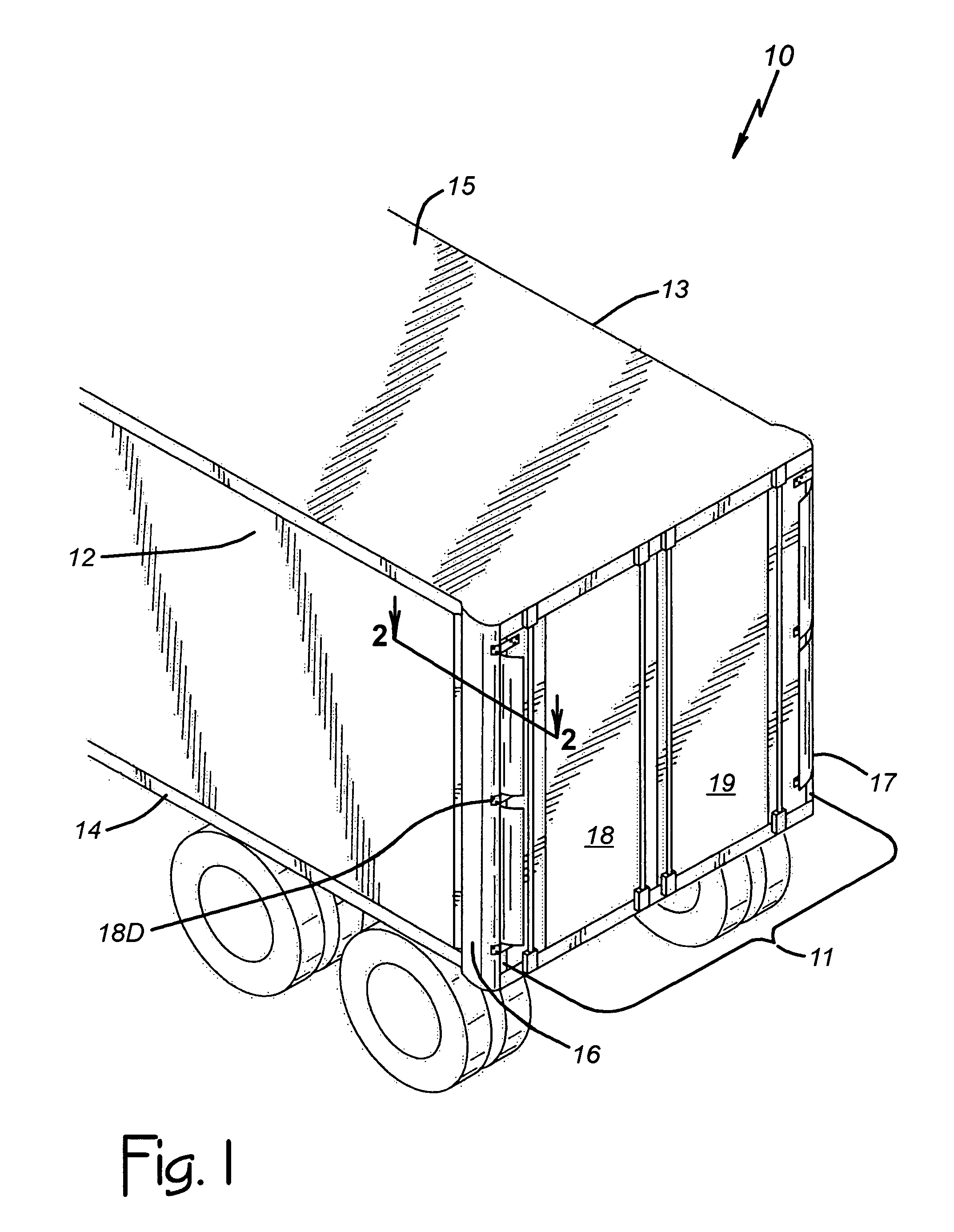
[0021]FIG. 1 of the drawings is a perspective view of a portion of a semi-trailer enclosure 10 constructed according to the invention. Generally, the enclosure 10 includes a rearward end portion 11 that extends vertically between the levels of floor and roof portions 14 and 15 of the enclosure 10. The rearward end portion 11 extends laterally between opposite left and right sidewalls 12 and 13 also, as indicated by a bracket in FIG. 1. The left and right sidewalls 12 and 13 extend vertically in horizontally spaced-apart positions between the levels of the floor and roof portions 14 and 15, and rearwardly to the rearward end portion 11. Those components of the enclosure 10 may be similar in many respects to existing semi-trailer enclosures.

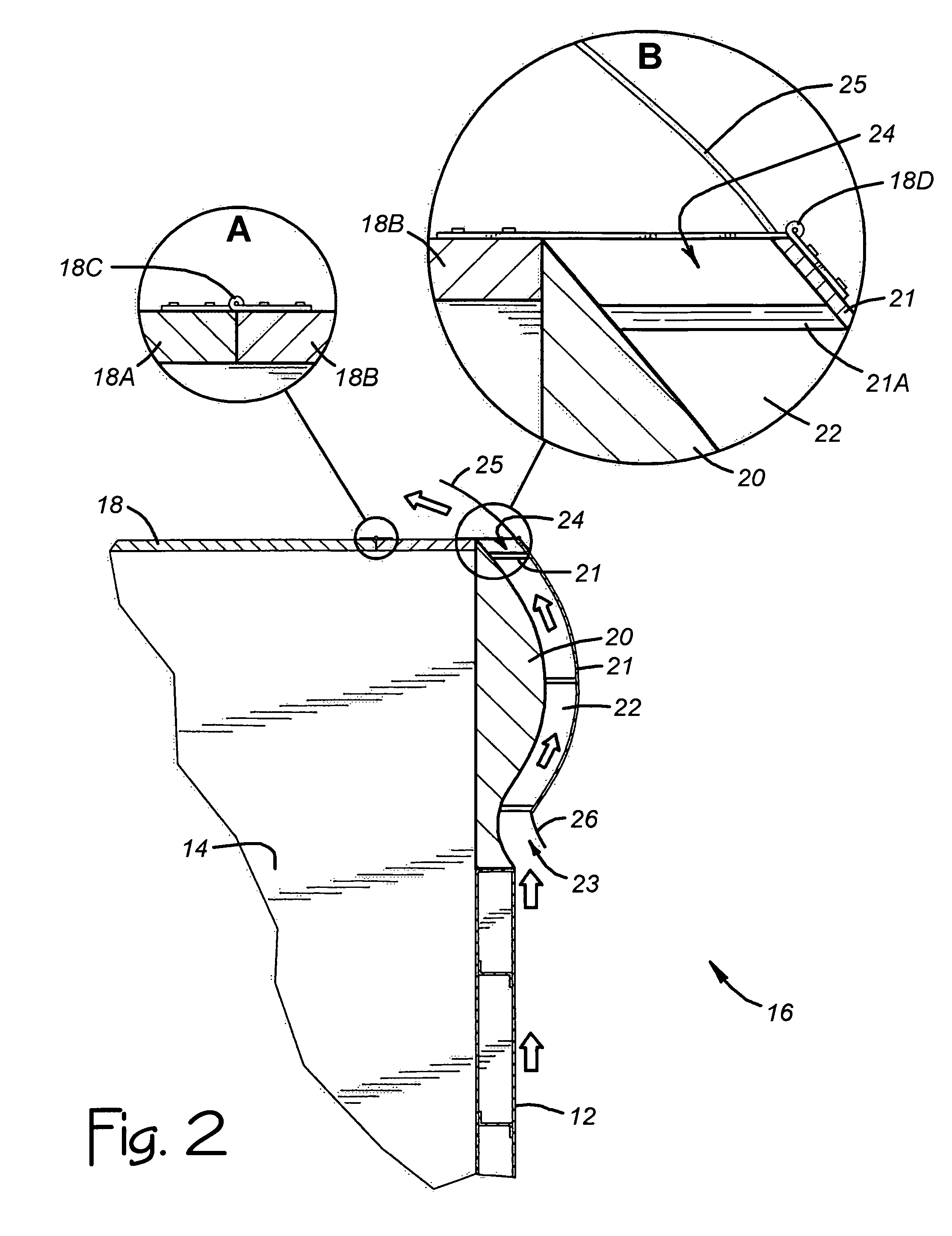
[0022]Unlike existing semi-trailer or other cargo vehicle enclosures, however, the enclosure 10 has built-in drag reducing components. According to a major aspect of the invention, the left sidewall 12 includes a left rearward corner portion 16, th...


PUM


Abstract

A semi-trailer or other cargo vehicle enclosure includes a rearward end portion extending between opposite left and right sidewalls. The sidewalls include vertically extending rearward corner portions that define air passageways for directing rearwardly flowing air from alongside the sidewalls toward a region of low pressure behind the rearward end portion of the enclosure. Preferably, the rearward corner portions include vertically extending rearward corner posts and deflector components that are formed to cooperatively define circularly shaped passageways for gradual air-flow redirection, with the sidewall exterior surfaces and the deflector exterior surfaces being within prescribed maximum semi-trailer widths while the interior corner post spacing does not reduce the usual width of semi-trailer cargo space. Bi-folding doors open to wide-open positions that clear the deflectors.

Description

BACKGROUND OF THE INVENTION[0001]1. Technical Field[0002]This invention relates generally to the trucking industry and to methods and structure for improving vehicle aerodynamics for better fuel efficiency. It relates more particularly to a semi-trailer or other cargo vehicle having a rear end drag-reducing design.[0003]2. Description of Related Art[0004]The term “cargo vehicle” herein refers to a semi-trailer or other wheeled ground vehicle used for hauling cargo on roads and highways. A typical semi-trailer, for example, includes a large rectangularly shaped, box-like enclosure having a forward end, a rearward end, opposite left and right sidewalls, and opposite floor and roof portions. The left and right sidewalls extend from the forward end to left and right rearward corner portions of the enclosure, with the rearward end being somewhat flat extending transversely across the direction of forward vehicle travel between the left and right rearward corner portions.[0005]So configur...

Claims


Application Information

Patent Timeline
Patent Type & Authority Patents(United States)
IPC IPC(8): B62D35/00
CPCB62D35/001
Inventor FITZGERALD, JAMES P.
Owner FITZGERALD JAMES P
Why Eureka
Try Eureka