Heat treatment apparatus and method of manufacturing substrates

a technology of heat treatment apparatus and substrate, which is applied in the direction of lighting and heating apparatus, charge supports, furnaces, etc., can solve the problems of crystal defect (slippage) or warpage of substrates, and achieve the effect of reducing the risk of warping

Inactive Publication Date: 2009-12-01
KOKUSA ELECTRIC CO LTD
View PDF23 Cites 21 Cited by
  • Summary
  • Abstract
  • Description
  • Claims
  • Application Information

AI Technical Summary

Benefits of technology

[0030]According to the first characteristic of the present invention, since at least one non-contact portion which communicates with the outside without being contact with the substrate is provided on the substrate placing plane of the plate member which supports the substrate so as not to come into contact with the peripheral portion of the substrate, and the surface area of the non-contact portion is included in a range between 25% and 94% inclusive of the surface area of an area surrounded by an outer edge line of the substrate placing plane of the plate member, air existing between the substrate and the plate member may be released via the non-contact portion when placing the substrate on the plate member, whereby the slippage which occurs when placing the substrate on the supporting portion formed of the plate member can be positively prevented. According to the second characteristic of the present invention, since at least one non-contact portion which communicates with the outside without being contact with the substrate is provided on the substrate placing plane of the plate member for supporting the substrate so as not to come into contact with the peripheral portion of the substrate, and the heat capacity of the plate member is set to a range between 61 J / K and 103 J / K inclusive, the slip rate may fall within a practical range.

Problems solved by technology

However, in the supporting tool in such configuration, the entire weight of each substrate is supported only by the holding grooves at three points, and hence there is a problem such that when a thermal stress is applied abruptly to the substrates, crystal defect (slippage) or warp of the substrates may arise due to a tensile stress between the contact surfaces between the substrates and the holding grooves or a self-weight stress.

Method used


Image

  • Heat treatment apparatus and method of manufacturing substrates
  • Heat treatment apparatus and method of manufacturing substrates
  • Heat treatment apparatus and method of manufacturing substrates

Examples


first embodiment

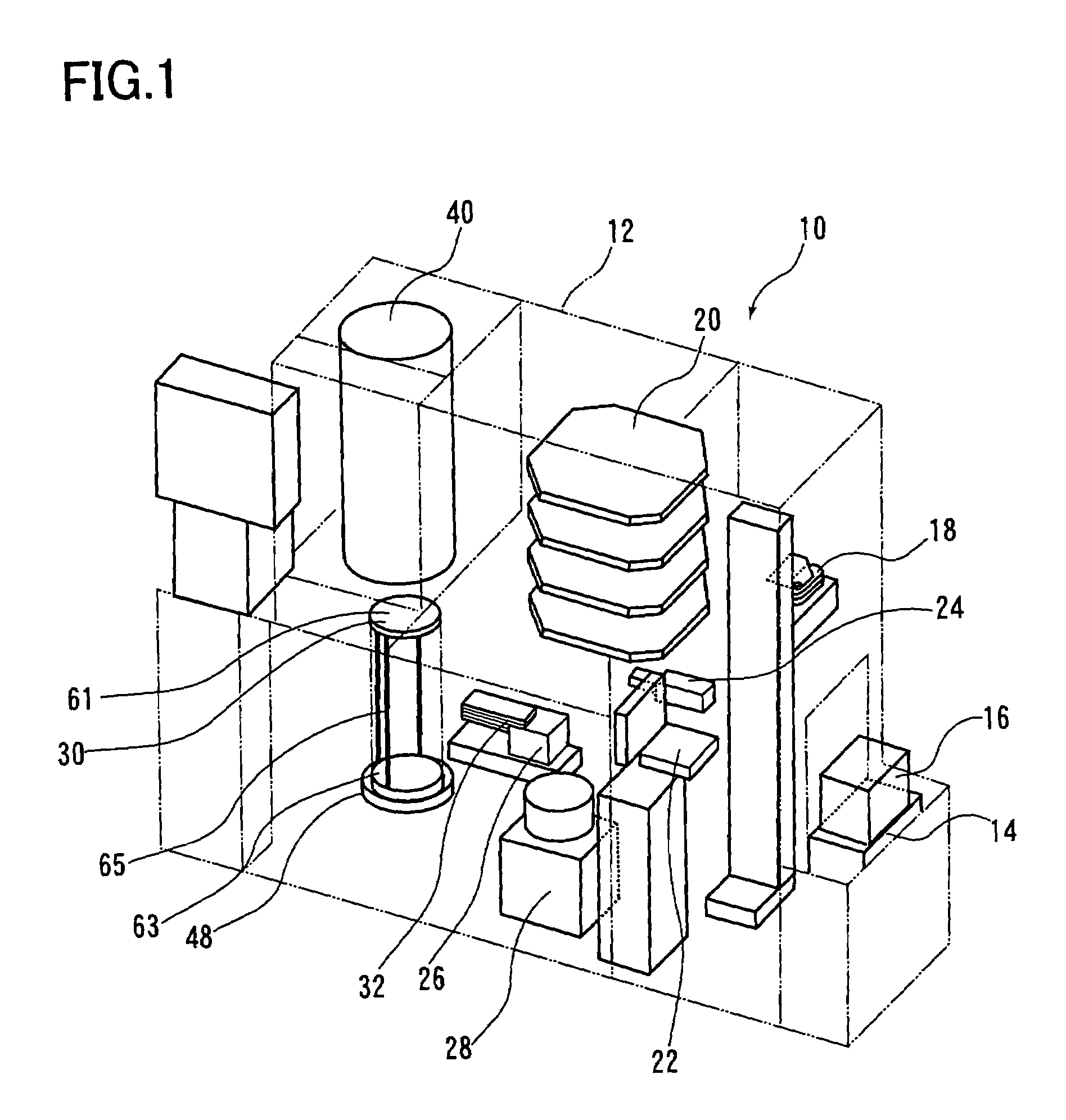
[0054]FIG. 1 shows a heat treatment apparatus 10 according to the present invention. The heat treatment apparatus 10 is a batch type vertically-installed heat treatment apparatus including a casing 12 in which a principal portion is arranged. A pod stage 14 is connected to the front side of the casing 12, and a pod 16 is transported to the pod stage 14. The pod 16 accommodates, for example twenty-five pieces of substrates and is mounted to the pod stage 14 in a state of being closed by a lid, not shown.

[0055]A pod transporting device 18 is arranged on the front side in the casing 12 at a position opposed to the pod stage 14. A pod shelf 20, a pod opener 22 and a substrate number sensor 24 are arranged in the vicinity of the pod transporting device 18. The pod shelf 20 is arranged above the pod opener 22, and the substrate number sensor 24 is arranged adjacently to the pod opener 22. The pod transporting device 18 transports the pod 16 among the pod stage 14, the pod shelf 20, and th...

second embodiment

[0103]the present invention will be described below on the basis of the drawings.

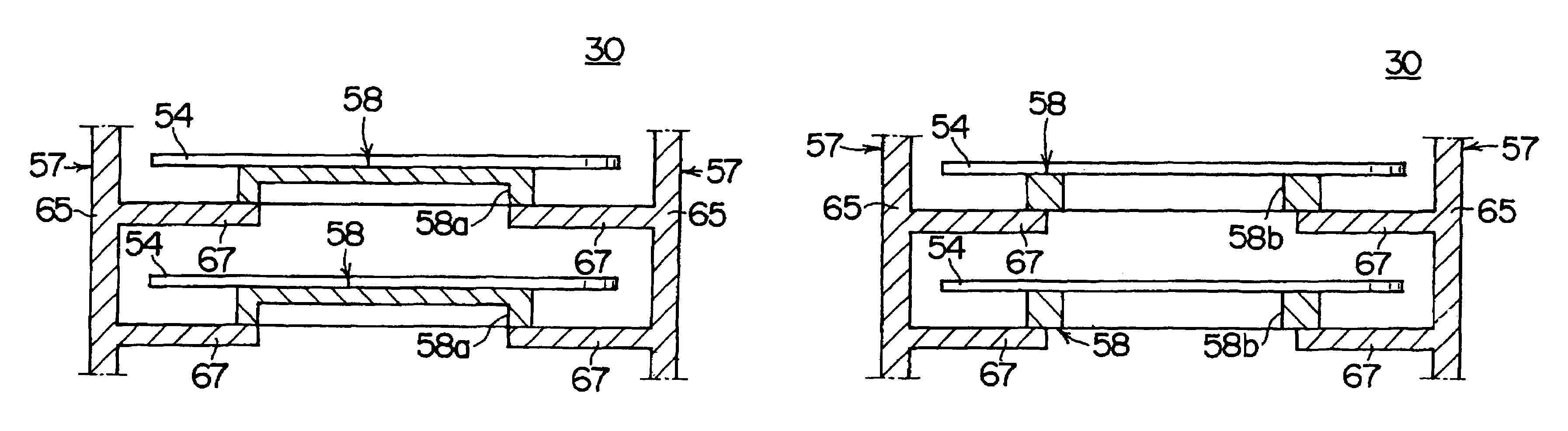
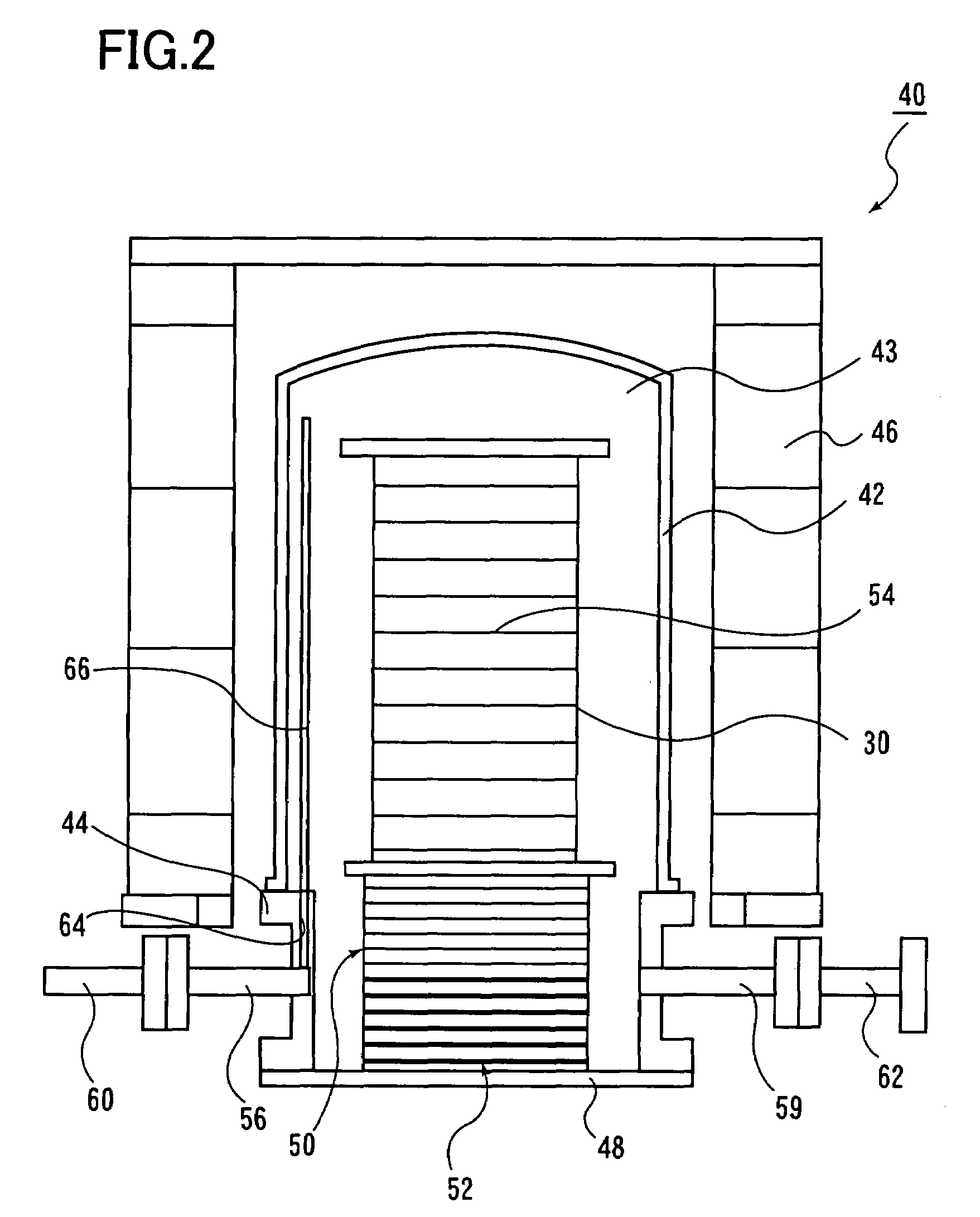
[0104]The general configurations of the heat treatment apparatus 10 and the reactor 40 in the second embodiment are the same as the aforementioned heat treatment apparatus 10 and the reactor 40 in the first embodiment described in conjunction with FIG. 1 and FIG. 2. The general structure of the supporting tool 30 in the second embodiment is the same as the supporting tool 30 in the first embodiment other than a spot facing 58a provided on the supporting portion 58 or the size of a through hole 58b. Different portions from the first embodiment will be mainly described here.

[0105]The supporting tool 30 in the second embodiment is shown in FIGS. 9 to 12.

[0106]The supporting portion 58 is provided with at least one spot facing 58a or through hole 58b for reducing the heat capacity of the supporting portion 58 itself as shown in FIGS. 9 to 12.

[0107]Referring now to FIG. 9, a first mode of the supporting port...


PUM


Abstract

A heat treatment device and a method of manufacturing substrates capable of reducing the slippage of the substrates when the substrates are supported on support parts comprising plate-like members. The device comprises a support device having the support parts in contact with the substrates and a body part supporting the support parts. Each of the support parts comprises the plate-like members supporting the substrate so as not to come into contact with the peripheral edge portion of the substrate, and a non-contact part communication with the outside without coming into contact with the substrate is formed in the substrate placing surface of the support part. The overall opening area of the portion of the non-contact part communicating with the outside is 25 to 94% of the overall area of the substrate placing surface.

Description

TECHNICAL FIELD[0001]The present invention relates to a heat treatment apparatus for applying a heat treatment to semiconductor wafers, glass substrates or the like, and a method of manufacturing substrates such as the semiconductor wafers or the glass substrates.BACKGROUND ART[0002]In the related art, a supporting tool in a vertically installed heat treatment apparatus includes a pair of upper and lower end plates, for example, three holding members disposed vertically between the both end plates so as to extend therebetween, and is configured to hold a number of holding grooves formed in the longitudinal direction at regular intervals on these three holding members so as to open toward each other, so that a plurality of substrates are arranged horizontally with the centers thereof aligned with each other by being inserted between the holding grooves of the three holding members. However, in the supporting tool in such configuration, the entire weight of each substrate is supported...

Claims


Application Information

Patent Timeline
Patent Type & Authority Patents(United States)
IPC IPC(8): F27D5/00
CPCH01L21/67109H01L21/68771H01L21/68735H01L21/22H01L21/324
Inventor SASAJIMA, RYOTANAKAMURA, IWAO
Owner KOKUSA ELECTRIC CO LTD
Why Eureka
Try Eureka