
Dual angled canopy retractable awning

Active Publication Date: 2009-12-08
CAREFREESCOTT FETZER
View PDF15 Cites 29 Cited by
  • Summary
  • Abstract
  • Description
  • Claims
  • Application Information

AI Technical Summary

Benefits of technology

"The present invention is an awning that can be mounted on a support surface, with the awning including a roller and support arms that allow the awning to extend in two distinct angles relative to horizontal. The awning can cover a wide area adjacent to the support surface and also provide shade and shelter from rain or the like over a relatively large area adjacent to the side of a mobile home or recreational vehicle. The technical effects of the invention include improved coverage and protection from weather, as well as improved aesthetics and functionality for outdoor living."

Problems solved by technology

A problem with slide-out units has resided in the accumulation of debris on the top wall of the slide-out unit when it is extended with such debris taking the form of dirt, leaves, or the like.

Method used


Image

  • Dual angled canopy retractable awning
  • Dual angled canopy retractable awning
  • Dual angled canopy retractable awning

Examples


Embodiment Construction

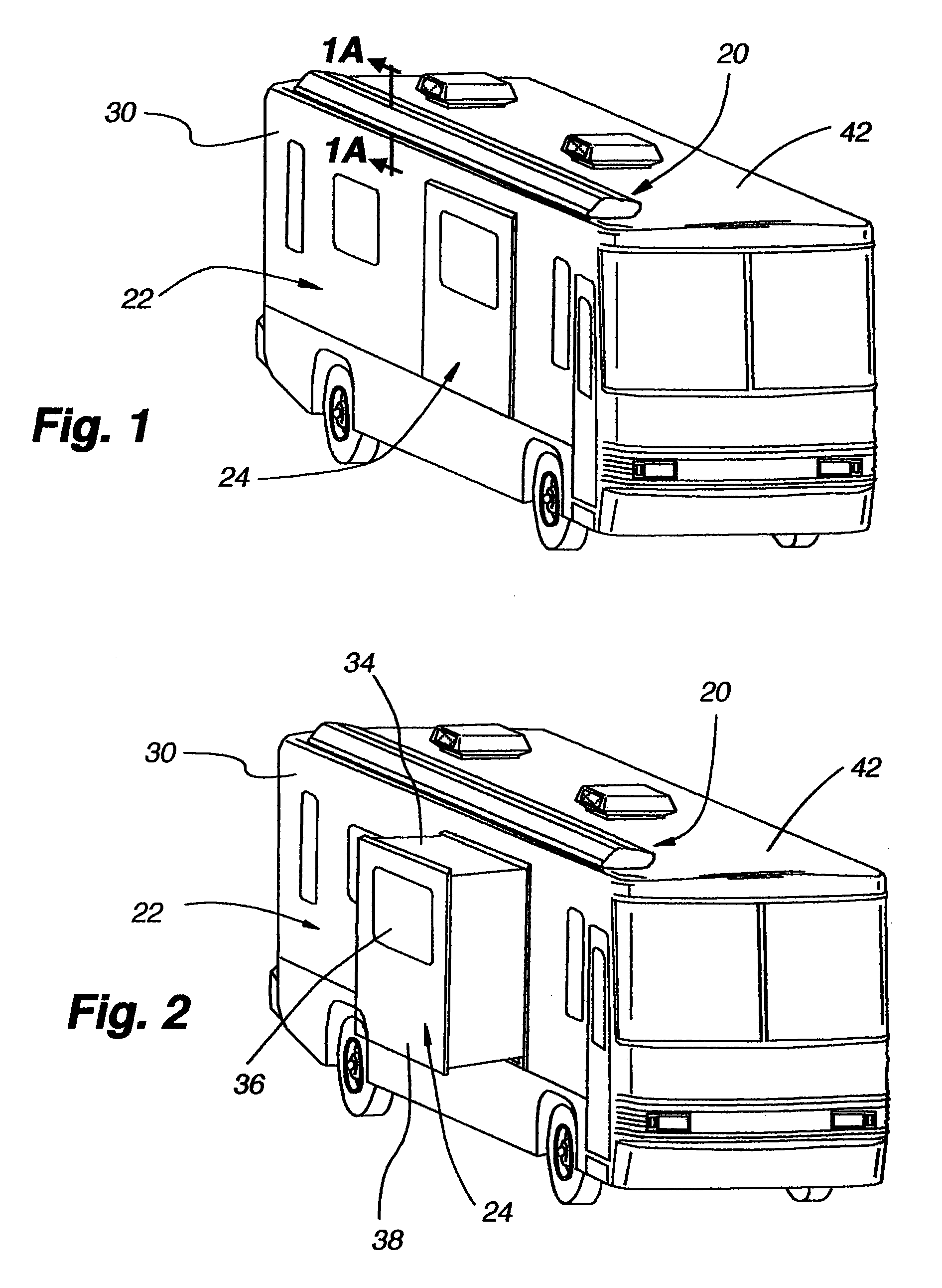
[0030]The retractable awning 20 of the present invention, while possibly finding use on permanent building structures, finds a particular use on mobile homes or recreational vehicles 22 having slide-out units 24 in the form of box-like structures which can be extended from the side of the vehicle and retracted back into the vehicle. Further, while the awning could be mounted on a vertical side wall or support structure, for purposes of the present disclosure, the awning has been described as being mounted on the roof of a recreational vehicle adjacent to a side of the vehicle having a slide-out unit disposed therein.

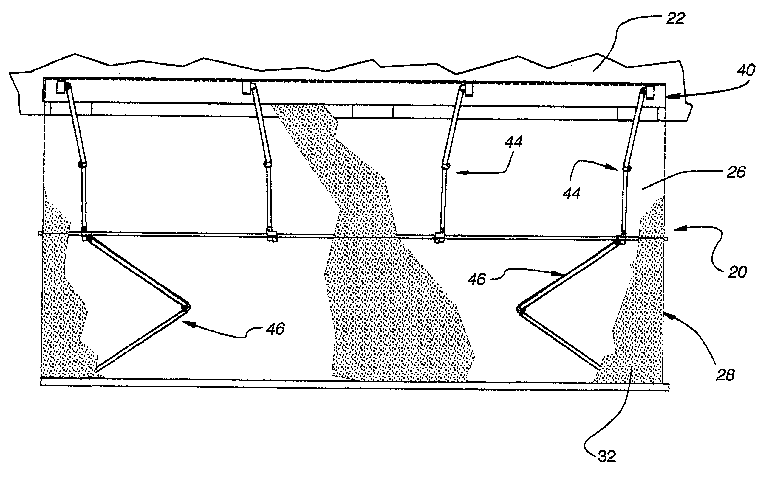
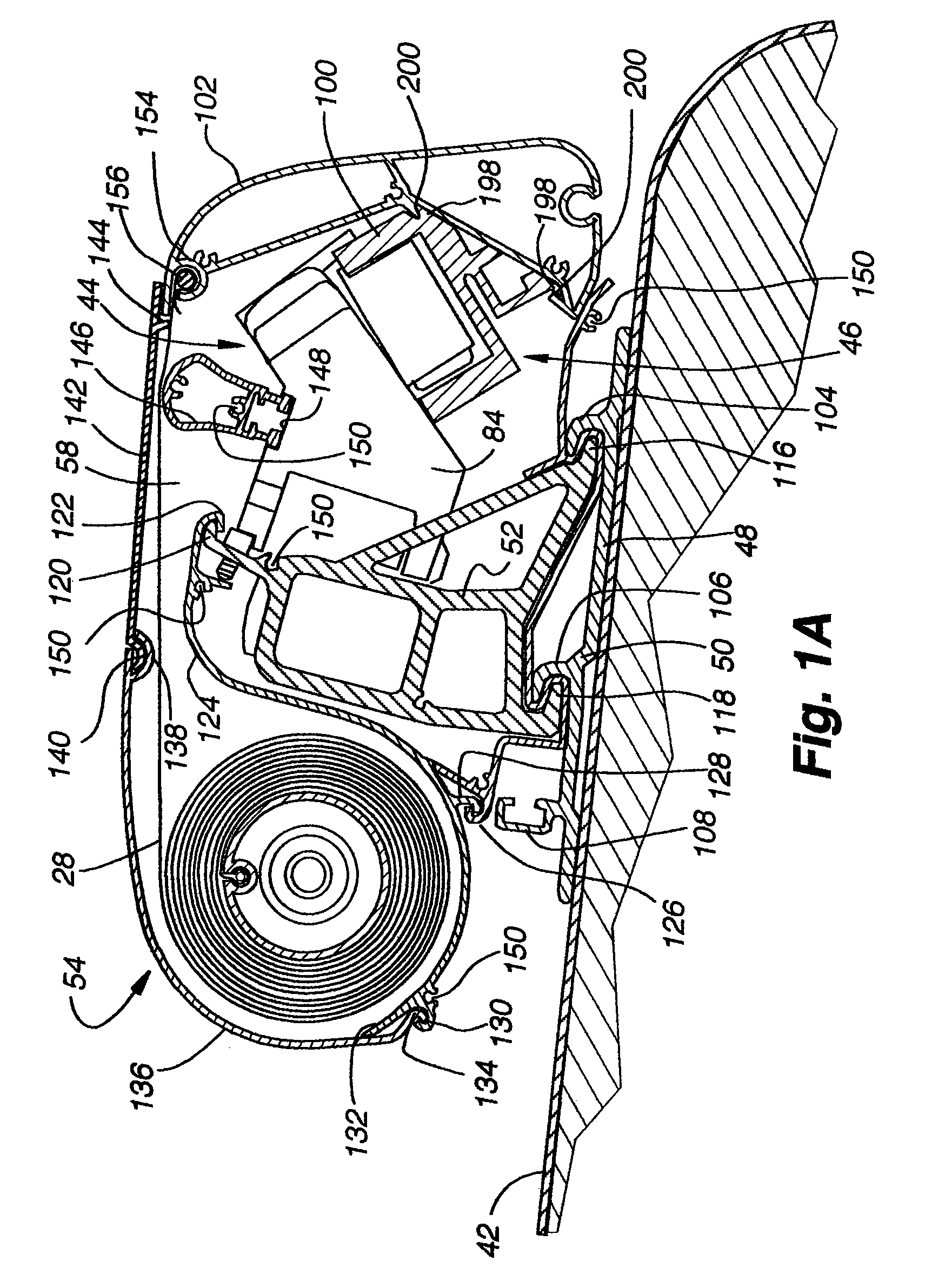
[0031]While the awning 20 is movable between a retracted position (FIGS. 1 and 2) and an indefinite number of extended positions, the extended positions might be divided into three desired positions shown for example in FIGS. 3, 4 and 5. In FIG. 3, the awning is shown in a first abbreviated extended position wherein an inner segment 26 of the canopy 28 of the awning form...


PUM


Abstract

A retractable awning includes a roller reversibly driven and mounted within a housing for support on a support structure and both inner and outer sets of pivotally interconnected support arms for supporting an awning canopy when extended. The inner set of support arms support the canopy beneath an inner segment of the canopy adjacent the support surface and are designed to deploy before the outer set of support arms with the outer set of support arms supporting the canopy beneath an outer segment of the canopy further away from the support surface than the inner segment. Both the inner and outer sets of support arms can be partially or fully deployed to regulate the extent to which the awning is extendible away from the support surface. The outer support arms are mounted for pivotal movement within a plane forming a different angle with horizontal than the inner set of support arms so the inner segment of the canopy above the inner set of support arms when extended forms a different angle with horizontal than does the outer segment of the awning canopy overlying the outer set of support arms when extended.

Description

CROSS REFERENCE TO RELATED APPLICATION[0001]This application claims priority to U.S. provisional application 60 / 821,677 filed Aug. 7, 2006 and is hereby incorporated by reference as if fully disclosed herein.BACKGROUND OF THE INVENTION[0002]1. Field of the Invention[0003]The present invention relates generally to a retractable awning for mounting on a support surface with the awning having a reversibly driven roller anchoring an inner edge of an awning canopy and inner and outer pairs of pivotal support arms that extend and retract with extension and retraction of the awning whereby the awning canopy forms two different angles relative to horizontal when fully extended.[0004]2. Description of the Relevant Art[0005]Retractable awnings have been in use for many years on building structures as well as mobile homes, recreational vehicles, and the like. The awnings are adapted to extend away from the side of the structure or vehicle to form shade adjacent the side thereof or be retracted...

Claims


Application Information

Patent Timeline
Patent Type & Authority Patents(United States)
IPC IPC(8): E04F10/06
CPCE04F10/0622E04F10/067E04F10/0648E04F10/0688E04F10/0662E04F10/0651
Inventor WAGNER, ROBERTRUTHERFORD, JEFFREY B.THOMPSON, SCOTT P.GAUDYN, ERWIN J.HOFFMAN, TODD
Owner CAREFREESCOTT FETZER
Learn More