Adjustable tilt mount

Inactive Publication Date: 2006-12-26
LEGRAND AV INC
View PDF92 Cites 209 Cited by
  • Summary
  • Abstract
  • Description
  • Claims
  • Application Information

AI Technical Summary

Benefits of technology

[0006]The display can be tilted about the pivot axis, which is parallel to the front surface of the display, through a range of angles defined by the arc. Because the pivot axis passes through the center of gravity of the display, the weight of the display is balanced in any one of the angular positions. No clamping or other adjustment is required to hold the display in any one of its tilted positions.

Problems solved by technology

Similarly, flat screen televisions can be placed in locations which were previously not practical locations.

Method used


Image

  • Adjustable tilt mount
  • Adjustable tilt mount
  • Adjustable tilt mount

Examples


first embodiment

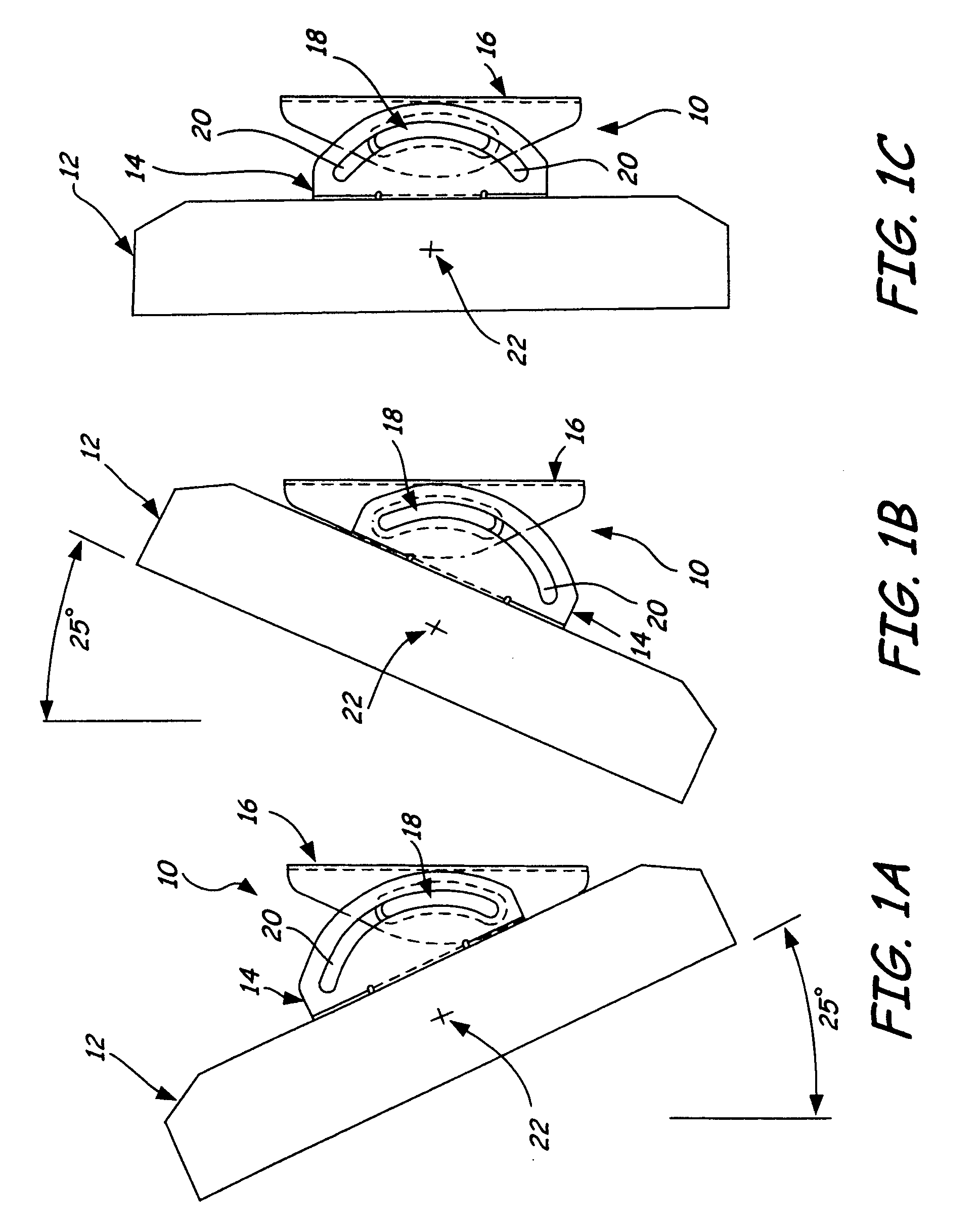
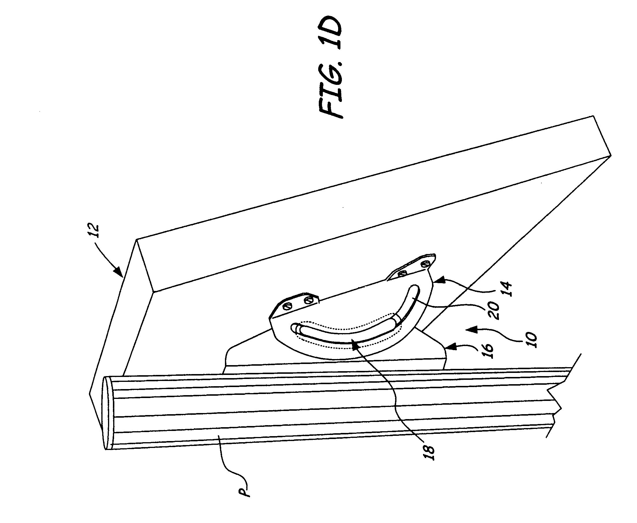
[0025]FIGS. 1A–1F show mounting system 10 of the present invention. In FIGS. 1A–1F, mounting system 10 supports display 12, which is a flat panel computer monitor or television at three different positions with respect to vertical.

[0026]Mounting system 10 has three major parts, mount bracket 14, support or wall bracket 16, and a pair of glides 18. Mount bracket 14 is attached to a back surface of monitor 12, while support 16 is connected either directly or indirectly to a support surface such as post P (or a wall).

[0027]Mount bracket 14 has a pair of arcuate slots 20 which define the range of sliding motion of mount bracket 14 with respect to support bracket 16. Glides 18 are carried by support bracket 16 and project into slots 20. Glides 18 ride within slots 20 to allow a sliding movement of mount 14 with respect to support 16. The path of the sliding movement is defined by the arc of slots 20. In the embodiment shown in FIGS. 1A–1F, the extent of angular rotation permitted by slid...

second embodiment

[0035]FIGS. 6A–6G show the present invention. Mounting system 100 supports display 102 in a wide variety of different positions and or orientations, as illustrated in FIGS. 6A–6G. Mounting system 100 includes mount assembly 104, support assembly 106, side knuckle 108, dog bone support arms 110 and 112, side knuckle 114, and wall plate 116.

[0036]As shown in FIGS. 6A–6G, mounting system 100 is supported from a vertical support, which in this case is pole P. Wall plate 116 is attached to pole P, and side knuckle 114 is attached to wall plate 116.

[0037]The inner end of dog bone 112 is pivotally connected to side knuckle 114 by tapered bearing 122. Adjustment screw 124 controls the drag of taper bearing 122 to control the rotation of dog bone 112 with respect to side knuckle 114.

[0038]The outer end of dog bone 112 is pivotally connected to the inner end of dog bone 110 by tapered bearing 126. Adjustment screw 128 controls the frictional drag produced by tapered bearing 126, and can be us...

third embodiment

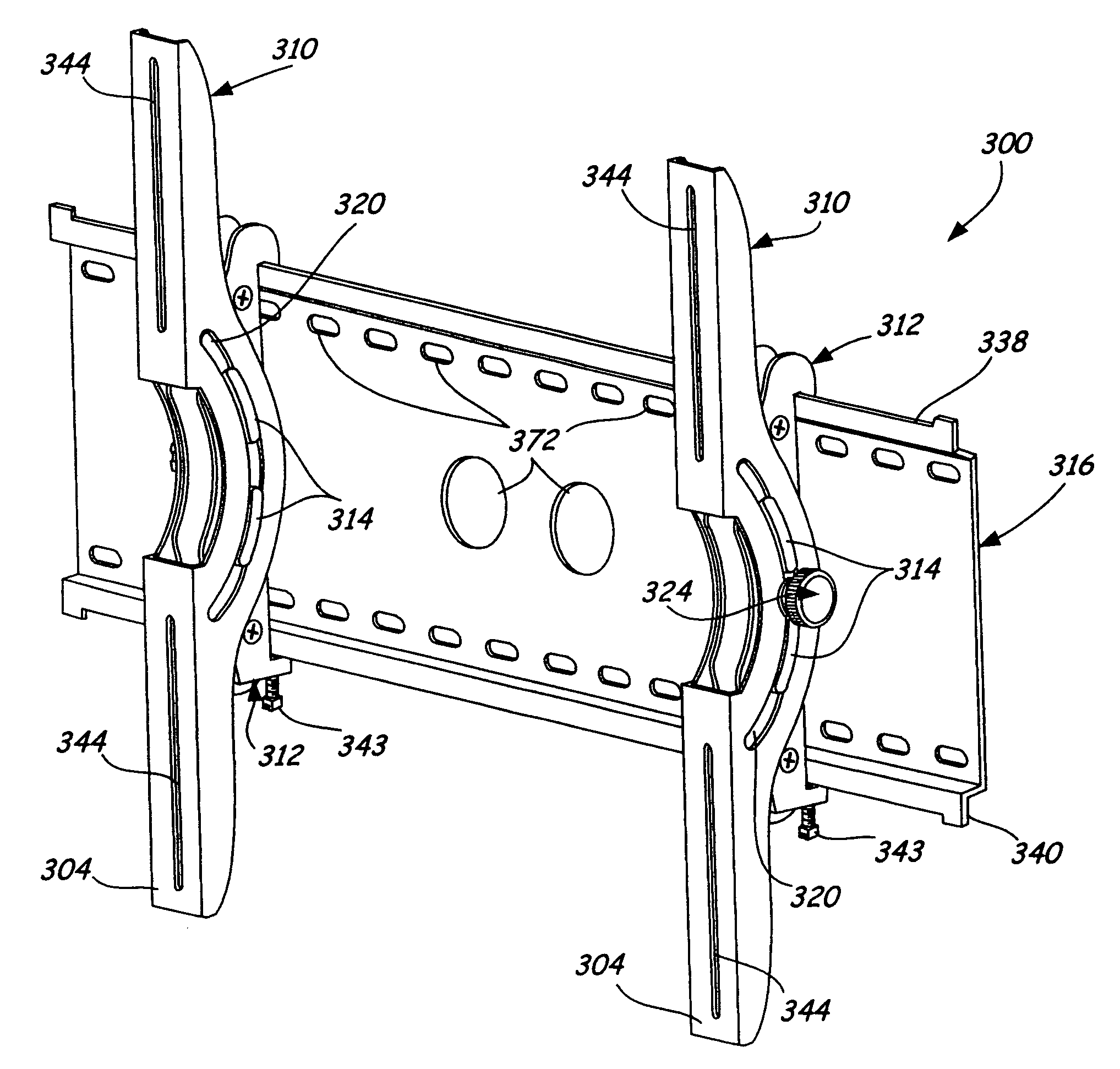
[0051]FIGS. 13A and 13B show the present invention. FIG. 13A is a side view of a mounting system 300, for use with larger displays 302. As illustrated in FIGS. 13A and 13B, the mounting system 300 again includes three major parts, mount bracket 310, support bracket 312, and a set of glides 314. Multiple mount brackets 310 can be used together to support larger sized displays 302 as shown in FIG. 13B. The mount bracket 310 is attached to a back surface of display 302. A front surface 304 of the mount bracket 310 acts as a mount plate to secure the mount bracket 310 to the display 302. Support bracket 312 is preferably mounted or secured to support plate 316, which in turn is secured to a wall or other support surface such as a post.

[0052]FIG. 14 is a perspective view of mount bracket 310 and support bracket 312. As illustrated in FIG. 14, mount bracket 310 has a pair of arcuate slots 320 in each of its first and second side walls 306 and 307 which define the range of sliding motion o...


PUM


Abstract

A mounting system for an interface such as a flat panel display such as a computer monitor or television allows the display to be pivoted about a virtual pivot axis which passes through a center of gravity of the display. The system includes a support which is connected directly or indirectly to a support surface and a mount which is connected to a back side of the display. The support and the mount are slidable with respect to one another through an arc which has the virtual pivot axis as its center.

Description

[0001]This application claims the benefit of U.S. Provisional Application No. 60 / 438,889, filed Jan. 9, 2003.BACKGROUND OF THE INVENTION[0002]The present invention relates to mounts for interface devices such as computer monitors and televisions. In particular, the present invention relates to a mount which allows the interface to be tilted about a generally horizontal pivot axis.[0003]The development of flat panel computer monitors and flat screen televisions offers the opportunity to replace large computer monitors and large television sets with displays having the same screen area but only a small fraction of the depth and weight. This allows computer monitors to be placed on desks without consuming a large portion of the desk top space. Similarly, flat screen televisions can be placed in locations which were previously not practical locations.[0004]The light weight and thin profile of the flat panel monitors and televisions allows them to be supported on a relatively small base,...

Claims


Application Information

Patent Timeline
Patent Type & Authority Patents(United States)
IPC IPC(8): E04G3/00A47F5/00A47K1/00F16C11/10F16M11/04F16M11/10F16M11/12F16M13/02F21V21/00
CPCF16C11/103F16M11/04F16M11/10F16M11/12F16M11/2014F16M13/02F16M13/022F16M2200/022F16M2200/027F16M2200/068Y10S248/92Y10S248/923
Inventor PFISTER, JOEL W.WOHLFORD, JAMES G.GREY, DOMINIC D.
Owner LEGRAND AV INC
Why Eureka
Try Eureka