Apparatus for the application or removal of railway track fasteners

a technology for railway track and attachments, applied in railway tracks, railway track construction, ways, etc., can solve the problems of difficult removal of clips, loss of flexibility, and corrosion of clips,

Active Publication Date: 2013-12-05
MELVELLE EQUIP CORP
View PDF10 Cites 8 Cited by
  • Summary
  • Abstract
  • Description
  • Claims
  • Application Information

AI Technical Summary

Benefits of technology

[0017]Preferably, the trolley also comprises a boom assembly to which the workhead is mounted, the boom assembly being pivotally mounted to the carriage for substantially vertical movement of the workhead. More preferably, the boom assembly includes adjustable pivots which provide for balanced weighting of the boom assembly depending on the weight of the workhead.

Problems solved by technology

Railway track fastening technology often relies on the use of basic hand tools, particularly where corrosion or binding between track components results in difficulty in removing or inserting clips.
In the harsh Australian environment and generally over time, clips become corroded and therefore difficult to remove as they disintegrate, lose flexibility or become ‘welded’ to the rail or sleeper through corrosion.
Removal of clips in these situations can be difficult and dangerous due to the need to improvise using a rivet punch and sledge hammer to impact the offending clip in order to dislodge and remove it.
Often these techniques result in occupational health and safety risks due to sprung steel clips becoming dangerous projectiles when freed suddenly.
Improvisation in the removal or installation process, using heavy tools such as sledge hammers, also results in the possibility for operator injury.
However, machines currently in the marketplace have several drawbacks:1. They often do not sufficiently contain the clip during the insertion or removal operation and the energy from the deformed clip can transform it into a projectile and endanger the operator or surrounding crew;2. The successful operation is dependent upon operator skill through alignment of the head with the clips; and3. Particularly with heavily corroded clips, the operator must place a relatively high force to the machine to dislodge the clip.

Method used


Image

  • Apparatus for the application or removal of railway track fasteners
  • Apparatus for the application or removal of railway track fasteners
  • Apparatus for the application or removal of railway track fasteners

Examples


Embodiment Construction

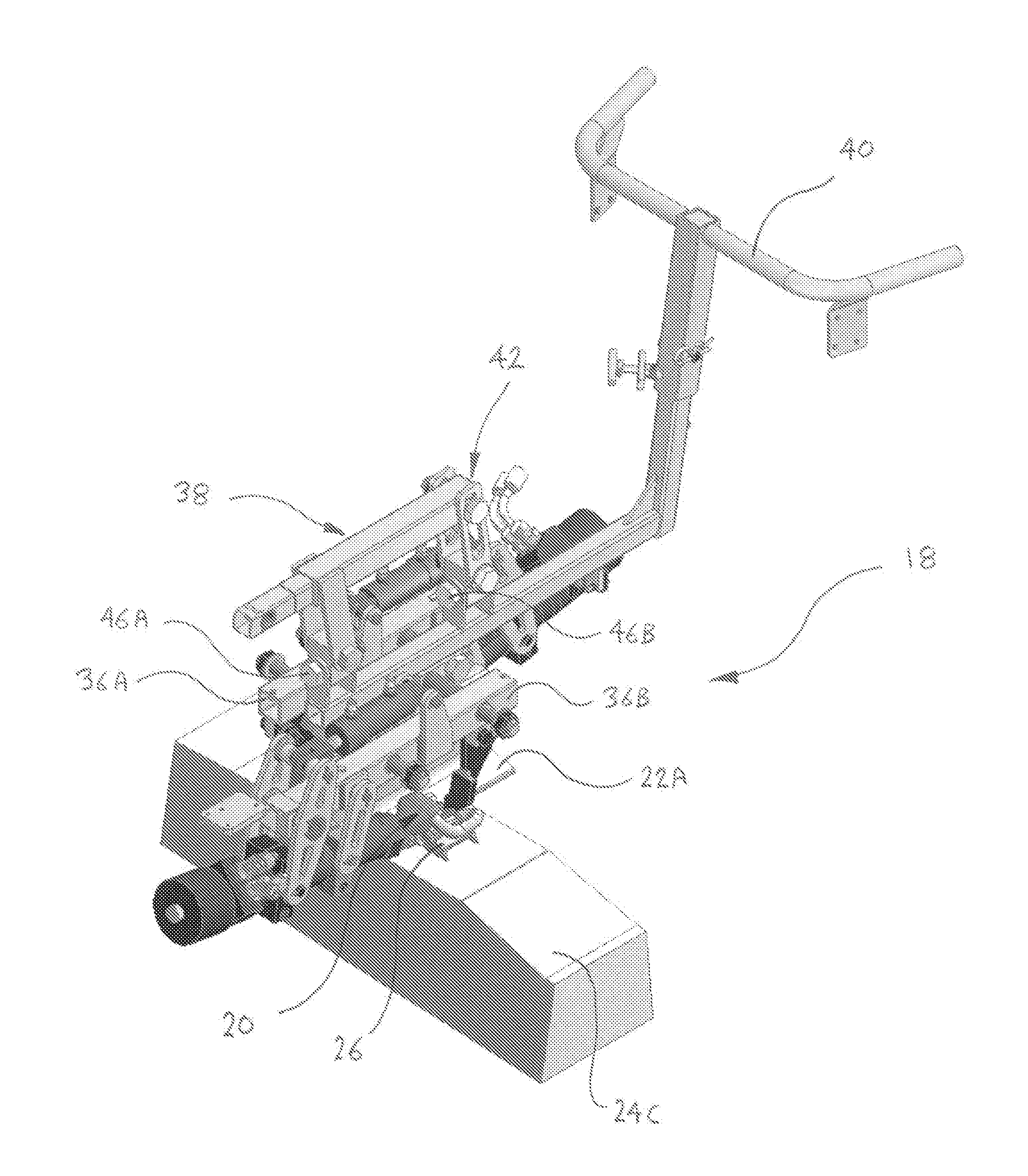
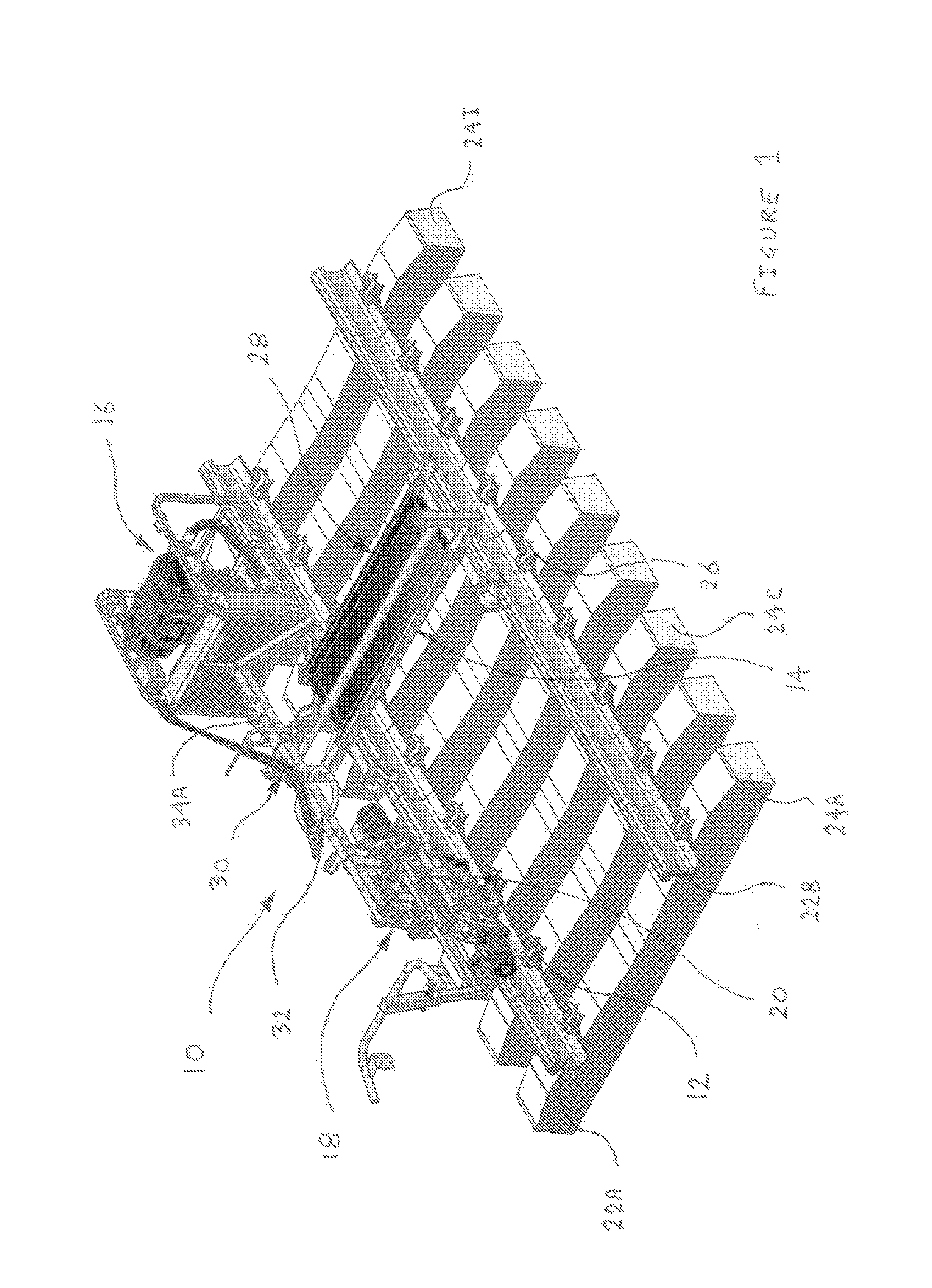
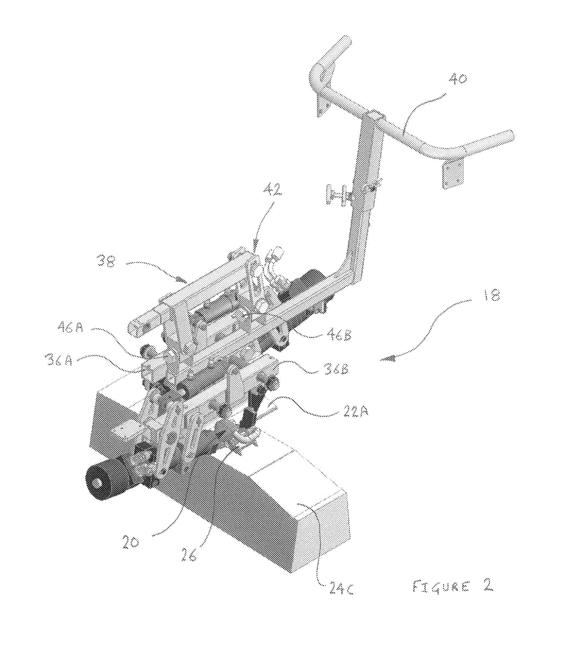
[0026]As best shown in FIG. 1, there is an apparatus 10 for the application or removal of one or more railway track fasteners such as 12. The apparatus 10 broadly comprises a support frame assembly 14, a drive assembly 16 mounted to the support frame assembly 14, and a workhead 18 operatively coupled to the drive assembly 16. The workhead 18 includes a tool 20 designed for applying or removing the fasteners such as 12 wherein the drive assembly 16 is powered to activate the workhead 18 and the associated tool 20 which contacts the fastener such as 12 in a hammering action.

[0027]The support frame assembly 14 in one aspect is adapted to locate on at least one or both of a pair of laterally spaced railway tracks such as 22A and 22B. The railway tracks 22A / B are anchored to underlying support sleepers such as 24A to 241 via sprung steel clips such as the fastener 12 inserted into sleeper fittings or collars such as 26. In another aspect of the invention there is provided a railway track...


PUM


Abstract

The present invention relates generally to an apparatus 10 for the application or removal of one or more railway track fasteners 12. The apparatus comprises a support frame assembly 14, a drive assembly 16 mounted to the support frame assembly 14, and a workhead 18 operatively coupled to the drive assembly 16. The workhead 18 includes a tool 20 designed for applying or removing the fasteners 12 wherein the drive assembly 16 is powered to activate the workhead 18 and the associated tool 20 which contacts the fastener 12 in a hammering action.

Description

FIELD OF THE INVENTION[0001]The present invention relates broadly to an apparatus for the application or removal of one or more railway track fasteners. The invention also relates generally to a railway track trolley such as that used to apply or remove railway track fasteners.BACKGROUND TO THE INVENTION[0002]Railway track is usually fixed to the underlying supporting sleeper made of timber, concrete or steel using a variety of fasteners including traditional heavy gauge coach screws into timber sleepers, or sprung steel clips of various designs inserted under load into sleeper fittings or collars on both sides of each track. Railway track fastening technology often relies on the use of basic hand tools, particularly where corrosion or binding between track components results in difficulty in removing or inserting clips. In the harsh Australian environment and generally over time, clips become corroded and therefore difficult to remove as they disintegrate, lose flexibility or becom...

Claims


Application Information

Patent Timeline
Patent Type & Authority Applications(United States)
IPC IPC(8): E01B29/24
CPCE01B29/24E01B29/29
Inventor MELVELLE, ANDREW JOHN
Owner MELVELLE EQUIP CORP
Why Eureka
Try Eureka