Fan blade wheel

A wind impeller and fan technology, applied in the direction of mechanical equipment, machines/engines, liquid fuel engines, etc., can solve the problems of not effectively improving the aerodynamic performance and acoustic indicators of the fan, increasing the manufacturing cost of the ribs, and increasing the centrifugal force of the blades, etc. , to achieve the effects of increasing the effective work area, promoting stability, and a reasonable center of gravity position

Inactive Publication Date: 2014-01-01
浙江科贸智能机电股份有限公司
View PDF8 Cites 7 Cited by
  • Summary
  • Abstract
  • Description
  • Claims
  • Application Information

AI Technical Summary

Problems solved by technology

However, the inner chord strength of this utility model is insufficient, and it is variable after long-term windward rotation. The use of reinforcing ribs in the fixed part of the blade and the hub increases the manufacturing cost, and also increases the centrifugal force of the blade, and the rotation stability decreases. The increased centrifugal force and stability The swing caused by the reduction may break the blade and affect its service life. At the same time, its structure only considers the improvement of the overall stiffness and strength of the blade, and does not effectively improve the fan's requirements for aerodynamic performance and acoustic indicators. Therefore, it is necessary to use the structure make further improvements

Method used


Image

  • Fan blade wheel
  • Fan blade wheel
  • Fan blade wheel

Examples


Embodiment Construction

[0024] The present invention will be further described in detail below in conjunction with the accompanying drawings and embodiments.

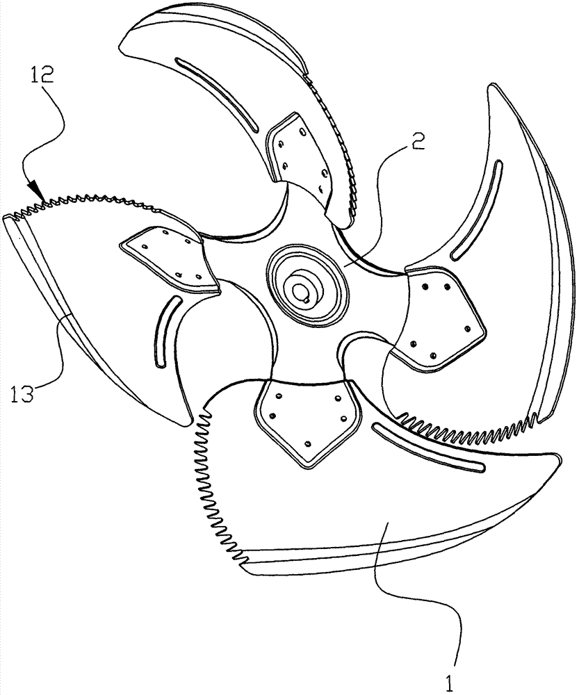
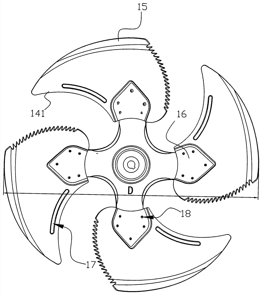
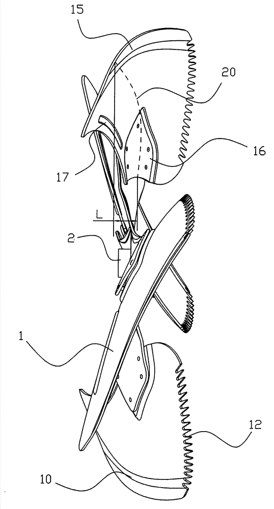
[0025] Such as Figure 1 to Figure 8 As shown, the wind impeller of the fan in this embodiment includes a blade 1 and a hub 2 linked with the output shaft of the motor. The blades 1 are distributed on the hub 2, and each blade 1 has an outer chord 13 wide and an inner chord 14 is narrow, and a streamlined flap 15 is provided on the blade 1 at the position of the outer chord 13, and the flap 15 extends to the outer chord 13 from the position where the blade tip extends into the outer chord 13 by 3%-30% of the length At the rear end, the trailing edge 12 of each blade 1 adopts a zigzag shape that can reduce rotational noise, and the outlet end of the blade 1 (ie, the trailing edge 12) is toothed, and the number of teeth adopts a prime number. The vortex flow loss at the outlet of the blade 1 is effectively reduced, the operating condition is re...


PUM


Abstract

A fan blade wheel comprises blades (1) and a hub (2), wherein the blades (1) are distributed on the hub (2), each of the blades (1) is provided with a wide outer chord (13) and a narrow inner chord (14), the blade (1) positioned at the position of the outer chord (13) is provided with a fairshaped flap (15) which begins to extend to the rear end of the outer chord (13) from the position where the blade tip extends into 3%-30% of the length of the outer chord (13), and the rear edge (12) of each of the blades (1) is in a sawtooth shape. The fan blade wheel is characterized in that the inner chord (14) comprises a first inner chord (141) and a second inner chord (142), wherein a concave portion (16) is arranged on the surface of the blade (1) close to the second inner chord (142), the back surface at the bottom of the concave portion protrudes outwards from the other surface of the blade, and a connection mechanism connected with the hub (2) is arranged on the concave portion (16). The fan blade wheel has the advantages of being reasonable in structural design, high in operation stability, long in service life and good in application effect. By means of the fan blade wheel, the strength of the blades is high, energy is saved, and noise is low.

Description

technical field [0001] The invention relates to the technical field of an axial flow fan, in particular to a wind impeller of a fan with high structural strength and firmly fixed blades. Background technique [0002] With the rapid development of the country's economic construction, the air-conditioning system is becoming more and more popular. The evaporative condenser in the air-conditioning system is a very important unit in the entire air-conditioning system. The performance of the cooling fan directly affects the operation effect of the air conditioning system. The ultra-low-noise axial-flow fans for air-conditioning condensers are required to be compact in size, light in weight, and have good aerodynamic performance and noise indicators. Since the operation of air-conditioning fans is mainly in winter and summer, the operating conditions are different, so new requirements are put forward for the average operating efficiency of the fans in multiple working conditions. ...

Claims


Application Information

Patent Timeline
Patent Type & Authority Applications(China)
IPC IPC(8): F04D29/38
Inventor 裘霖富刘伟张职锋张明仁章祺良
Owner 浙江科贸智能机电股份有限公司
Why Eureka
Try Eureka