Suspension of disc drive

a disc drive and suspension technology, applied in the direction of maintaining the head carrier alignment, recording information storage, instruments, etc., can solve the problems of increasing the mass of the suspension, affecting the properties of the suspension, and bending stress, so as to achieve a good balance and reduce the weight

Active Publication Date: 2008-04-15
NHK SPRING CO LTD
View PDF20 Cites 10 Cited by
  • Summary
  • Abstract
  • Description
  • Claims
  • Application Information

AI Technical Summary

Benefits of technology

[0012]Accordingly, the object of this invention is to provide a suspension for disc drive, in which the weights o

Problems solved by technology

Possibly, therefore, bending stress may develop in the wired flexure and influence the properties of the suspension.
If the conventional hinge member is used, therefore, it increases the

Method used


Image

  • Suspension of disc drive
  • Suspension of disc drive
  • Suspension of disc drive

Examples


first embodiment

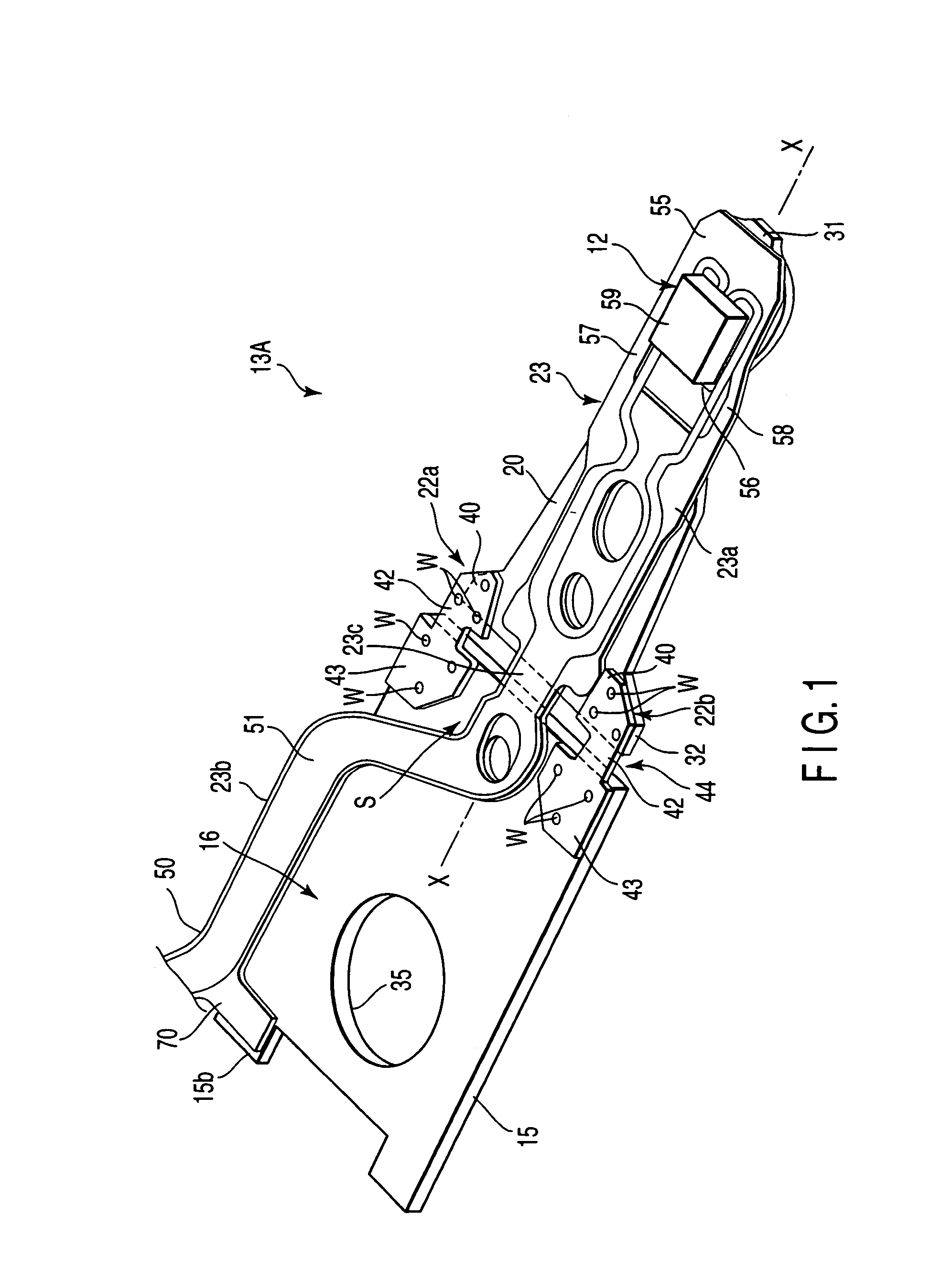
[0023]this invention will now be described with reference to FIGS. 1 to 3.

[0024]A hard disc drive (HDD) 10 shown in FIG. 3 comprises discs 11 for use as recording media, suspensions 13A for disc drive each having a head portion 12, arms (actuator arms) 14 fitted individually with the suspensions 13A, etc. The head portion 12 is used magnetically to record and read information to and from a recording surface of each disc 11. A positioning motor (not shown) turns the arms 14 around a shaft (not shown).

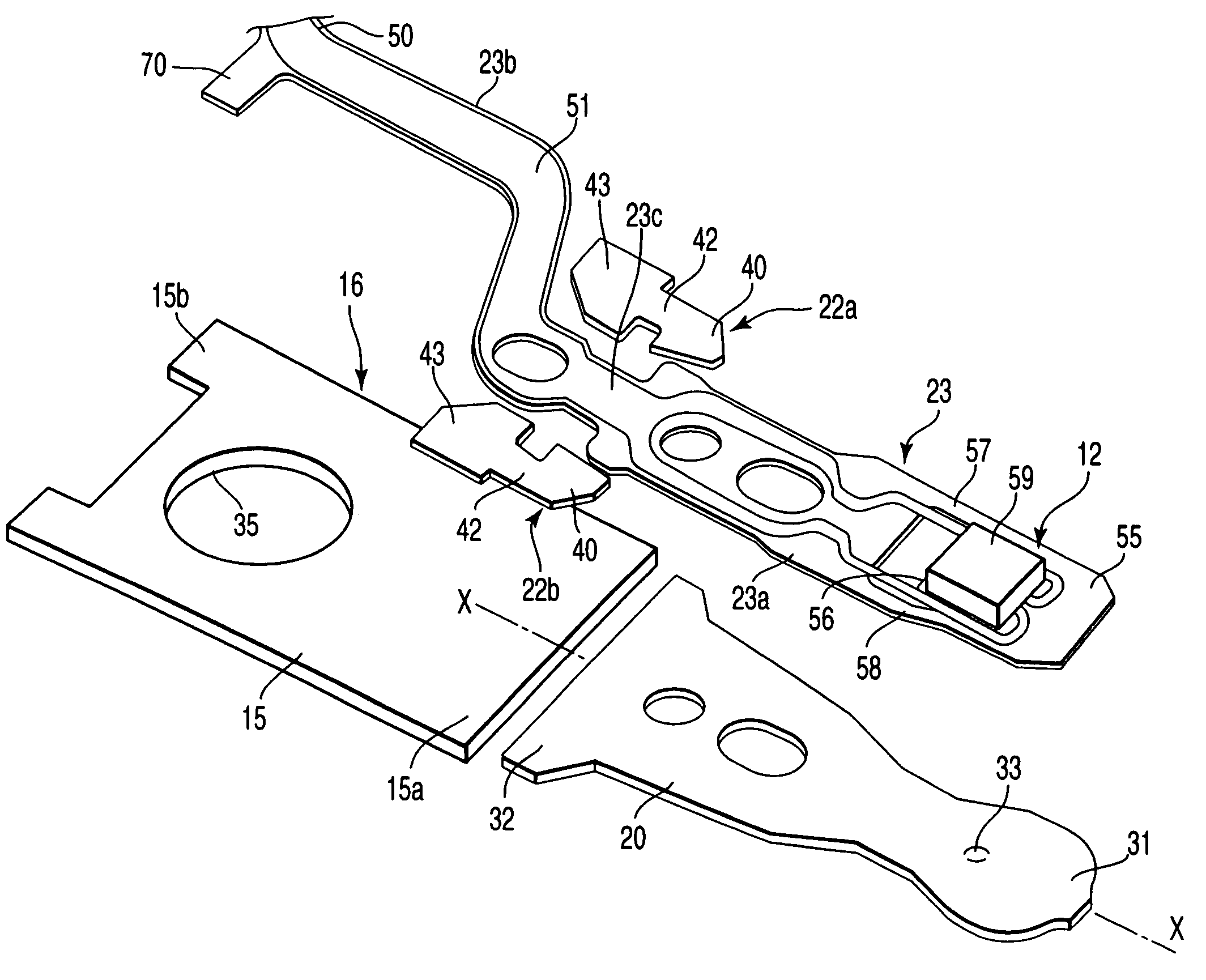
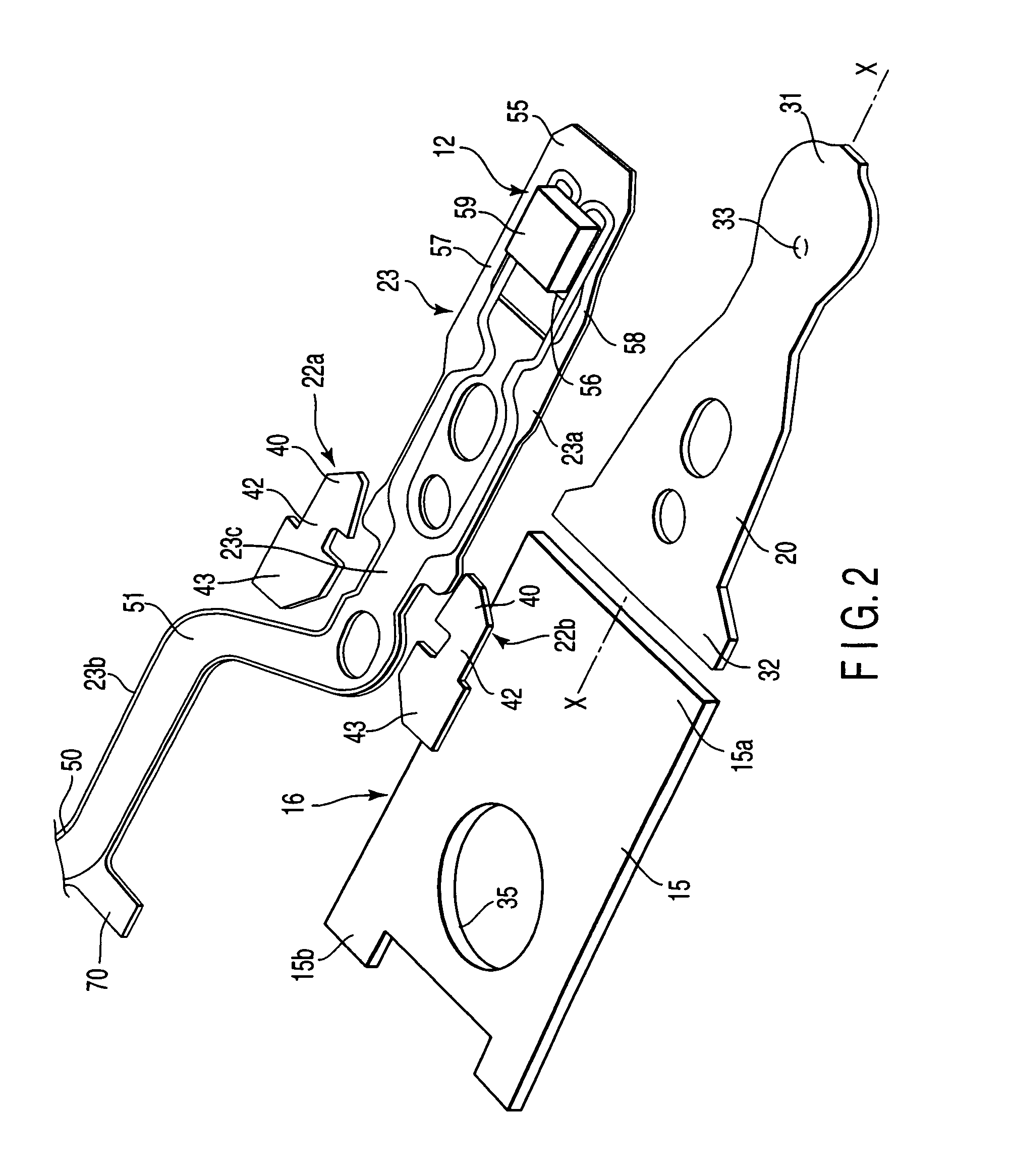
[0025]As shown in FIGS. 1 and 2, each suspension 13A is provided with a base portion 16 having a base plate 15, a load beam 20, a pair of independent hinge members 22a and 22b, a wired flexure 23 attached to the load beam 20. The wired flexure 23 extends along the load beam 20.

[0026]The load beam 20 has a front end portion 31 and a rear end portion 32, and is formed with a dimple 33 (shown in FIG. 3) that is located near the front end portion 31 and projects toward the flexure 23. The th...


PUM


Abstract

A suspension for disc drive has a base portion including a base plate, a load beam, a pair of hinge members, a wired flexure, etc. The wired flexure has a metal base and a wiring portion on the metal base. The hinge members are fixed overlapping the rear end portion of the load beam and the front end portion of the base plate. The wired flexure extends through a gap between the hinge members and ranges over the load beam and the base plate.

Description

CROSS-REFERENCE TO RELATED APPLICATIONS[0001]This application is based upon and claims the benefit of priority from prior Japanese Patent Application No. 2003-157176, filed Jun. 2, 2003, the entire contents of which are incorporated herein by reference.BACKGROUND OF THE INVENTION[0002]1. Field of the Invention[0003]This invention relates to a suspension for a disc drive contained in an information processor, such as a personal computer.[0004]2. Description of the Related Art[0005]A hard disc drive (HDD) for recording and reading information to and from a rotating magnetic disc, magneto-optical disc, etc. has a carriage that can turn around a shaft. A positioning motor turns the carriage around the shaft. The carriage comprises an actuator arm, a suspension on the distal end portion of the arm, a head portion including a slider on the suspension, etc.[0006]If the disc rotates, the slider on the distal end portion of the suspension slightly lifts above the surface of the disc, and an ...

Claims


Application Information

Patent Timeline
IPC IPC(8): G11B5/48G11B21/16G11B5/60G11B21/21
CPCG11B5/4833
Inventor TAKIKAWA, KENICHISAITO, NORIYUKIHANYA, MASAO
Owner NHK SPRING CO LTD
Why Eureka
Try Eureka