Ion generating unit and ion generating apparatus

a technology of generating unit and generating apparatus, which is applied in the direction of emergency protective arrangement details, electrically stable charges, and arrangements responsive to excess voltage, etc., can solve the problems of high cost of manufacturing the ion generating apparatus and the inability to selectively generate only negative ions

Active Publication Date: 2009-12-22
MURATA MFG CO LTD
View PDF19 Cites 1 Cited by
  • Summary
  • Abstract
  • Description
  • Claims
  • Application Information

AI Technical Summary

Benefits of technology

[0009]To overcome the problems described above, preferred embodiments of the present invention provide an ion generating unit and an ion generating apparatus that can generate negative ions or positive ions through the application of a low voltage.

Problems solved by technology

This requires a complicated power-supply circuit and insulation structure, so that a problem of the high cost of manufacturing the ion generating apparatus 110 arises.
Therefore, it is impossible to selectively generate only negative ions.

Method used


Image

  • Ion generating unit and ion generating apparatus
  • Ion generating unit and ion generating apparatus
  • Ion generating unit and ion generating apparatus

Examples


Embodiment Construction

[0036]An ion generating unit and an ion generating apparatus according to preferred embodiments of the present invention are described below with reference to the drawings.

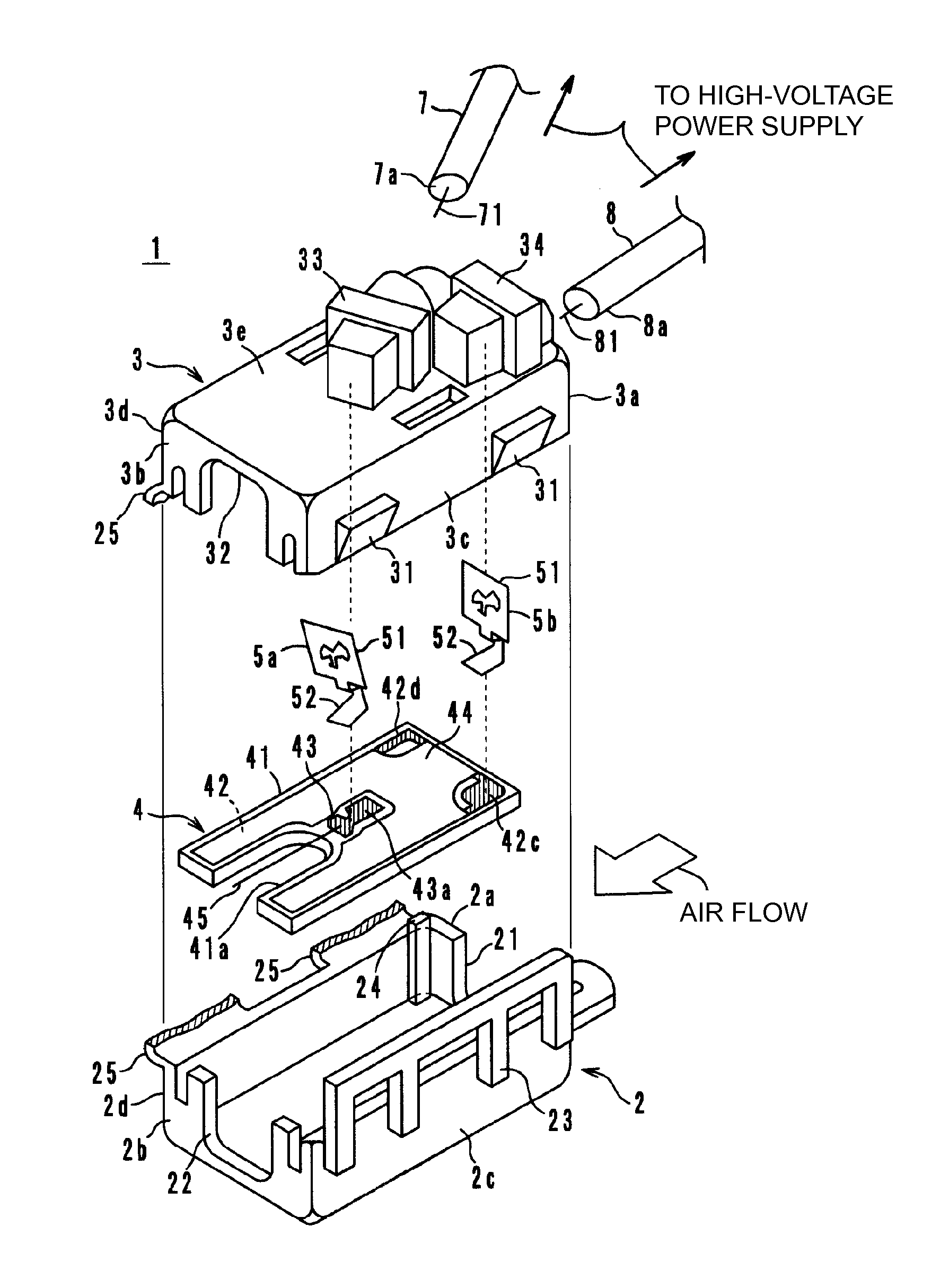
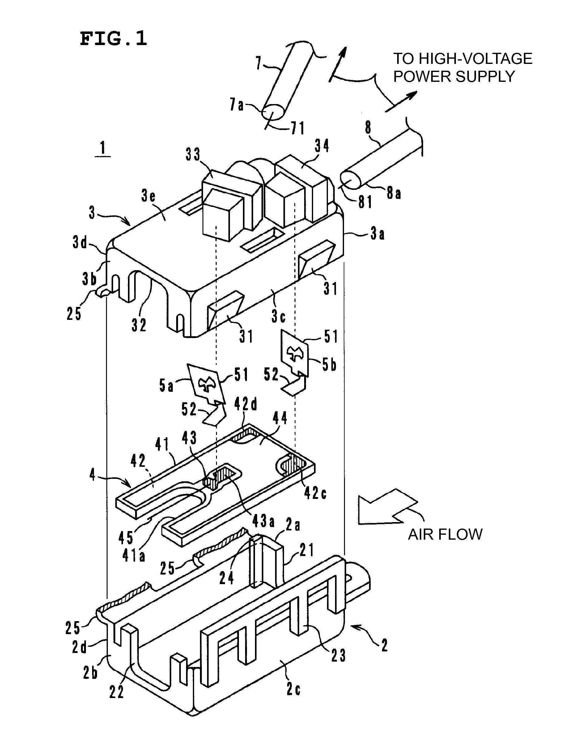
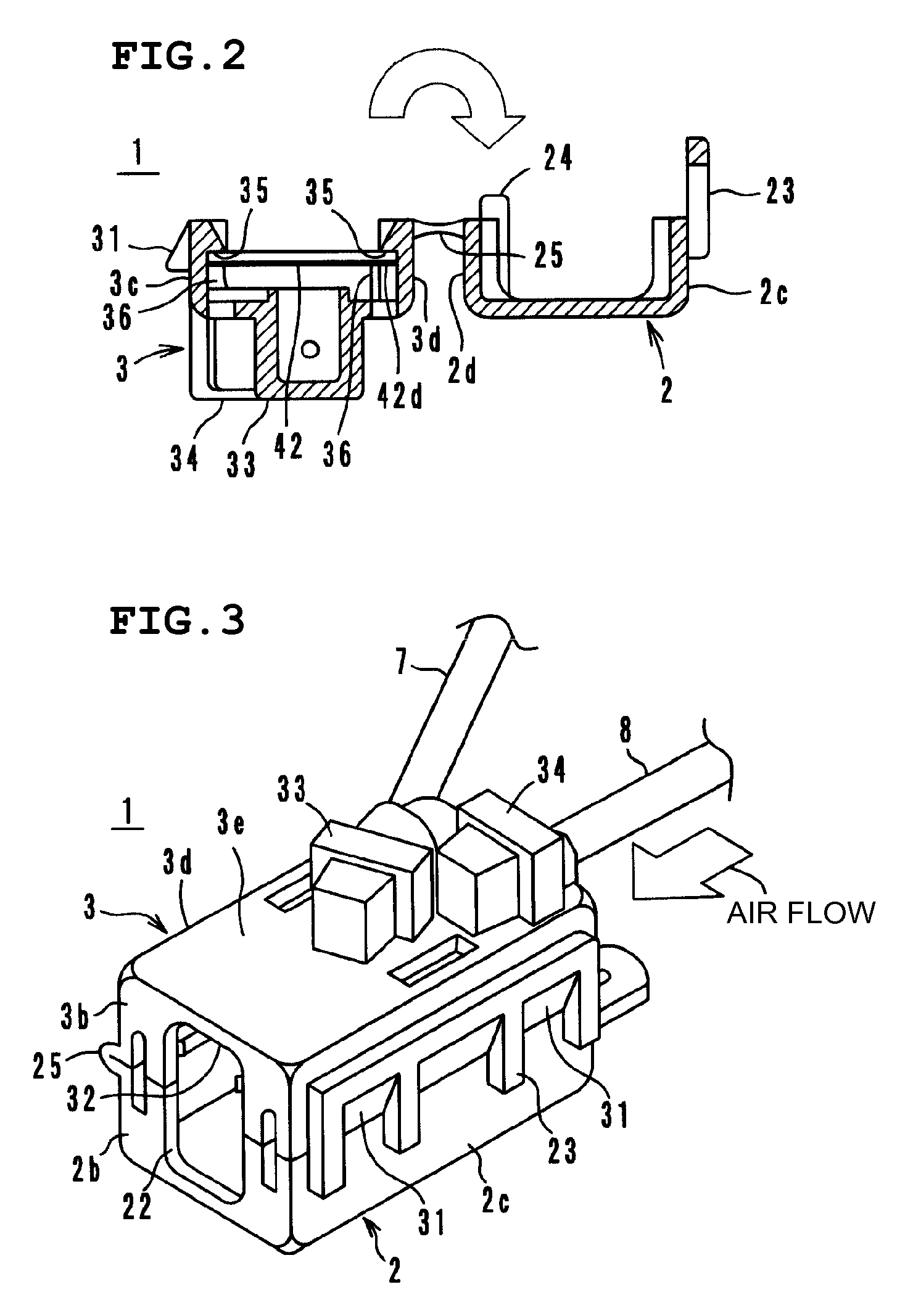
[0037]FIG. 1 is an exploded perspective view of an ion generating apparatus 1, FIG. 2 is a cross-sectional view thereof, and FIG. 3 is an external perspective view thereof. As illustrated in FIG. 1, the ion generating apparatus 1 includes an insulating casing in which a lower resin casing 2 and an upper resin casing 3 are integral with each other with a hinge 25 therebetween, an ion generating component 4, a first terminal 5a, a second terminal 5b, leads 7 and 8, and a high-voltage power supply. The insulating casing including the lower resin casing 2 and the upper resin casing 3, the ion generating component 4, the first terminal 5a, and the second terminal 5b defines an ion generating unit. In FIG. 1, the hinge 25 is illustrated in a vertically cut state.

[0038]The lower resin casing 2 is provided with an air int...


PUM


Abstract

An ion generating component includes, on an insulating substrate, a ground electrode, a high-voltage electrode, an insulating film on the surface of the ground electrode, and a linear electrode. The ground electrode is disposed at the outer region of the insulating substrate and includes a pair of legs, which are substantially parallel to the linear electrode, which is disposed between the legs. The ground electrode further includes a contact portion in contact with a terminal and an insulating casing contact portion in contact with the upper resin casing. The insulating film is disposed on substantially the entire surface of the insulating substrate so that the high-voltage electrode, the contact portion, and the insulating casing contact portion of the ground electrode remain uncovered.

Description

BACKGROUND OF THE INVENTION[0001]1. Field of the Invention[0002]The present invention relates to an ion generating unit and an ion generating apparatus for use in an ion generating circuit in, for example, an air cleaner or an air conditioner.[0003]2. Description of the Related Art[0004]One known ion generating apparatus of this kind is described in Japanese Unexamined Patent Application Publication No. 6-181087 (Patent Document 1). As illustrated in FIG. 12, an ion generating apparatus 110 includes a housing 120, a discharge electrode 112 mounted to the front surface of the housing 120, and an opposing electrode 114. A high-voltage power supply portion 118 is disposed on the top of the housing 120. The high-voltage power supply portion 118 incorporates a high-voltage generating circuit for applying an alternating-current high voltage between the discharge electrode 112 and the opposing electrode 114.[0005]The discharge electrode 112 includes a plurality of sawteeth 112a. The discha...

Claims


Application Information

Patent Timeline
Patent Type & Authority Patents(United States)
IPC IPC(8): H01T23/00
CPCH01T23/00
Inventor KATO, SHINJIYOSHIDA, YUKIHIKO
Owner MURATA MFG CO LTD
Why Eureka
Try Eureka