Solenoid valve

a solenoid valve and valve body technology, applied in valve details, valve arrangements, machines/engines, etc., can solve the problems of difficult separation of movable elements from magnetically-attracting surfaces, high stickiness of movable elements to magnetically-attracting surfaces, etc., to enhance the durability of solenoid valves and enhance response characteristics

Inactive Publication Date: 2016-05-03
KOGANEI
View PDF22 Cites 1 Cited by
  • Summary
  • Abstract
  • Description
  • Claims
  • Application Information

AI Technical Summary

Benefits of technology

[0012]According to the present invention, since a resin film is provided on the magnetically-attracting surface of the fixed iron core, which is exposed through an opening of the bottom surface of the resin case, the movable element does not abut directly on the magnetically-attracting surface, therefore, it is possible to enhance response characteristics at the time of separating the movable element from the attracting surface. Moreover, the movable element is opposed also to the case side abutting surface of the case bottom surface, and the movable element abuts on the resin film in a state of being opposed to the magnetically-attracting surface and the case side abutting surface, and therefore, the durability of the solenoid valve is able to be enhanced without partial wearing arising in the resin film and the case side abutting surface. In particular, when two magnetically-attracting surfaces are exposed on the bottom surface of the case with the fixed iron core formed in a U-shape, an area of the attracting surface provided in the movable element while being opposed to the magnetically-attracting surface is able to be made large, and partial wearing is able to be prevented from arising in the resin film and the case side abutting surface.

Problems solved by technology

When the movable element is made to collide against a magnetically-attracting surface directly, a tendency in which the movable element sticks to the magnetically-attracting surface may become high, and it may become difficult for the movable element to be separated from the magnetically-attracting surface.

Method used


Image

  • Solenoid valve
  • Solenoid valve
  • Solenoid valve

Examples


Embodiment Construction

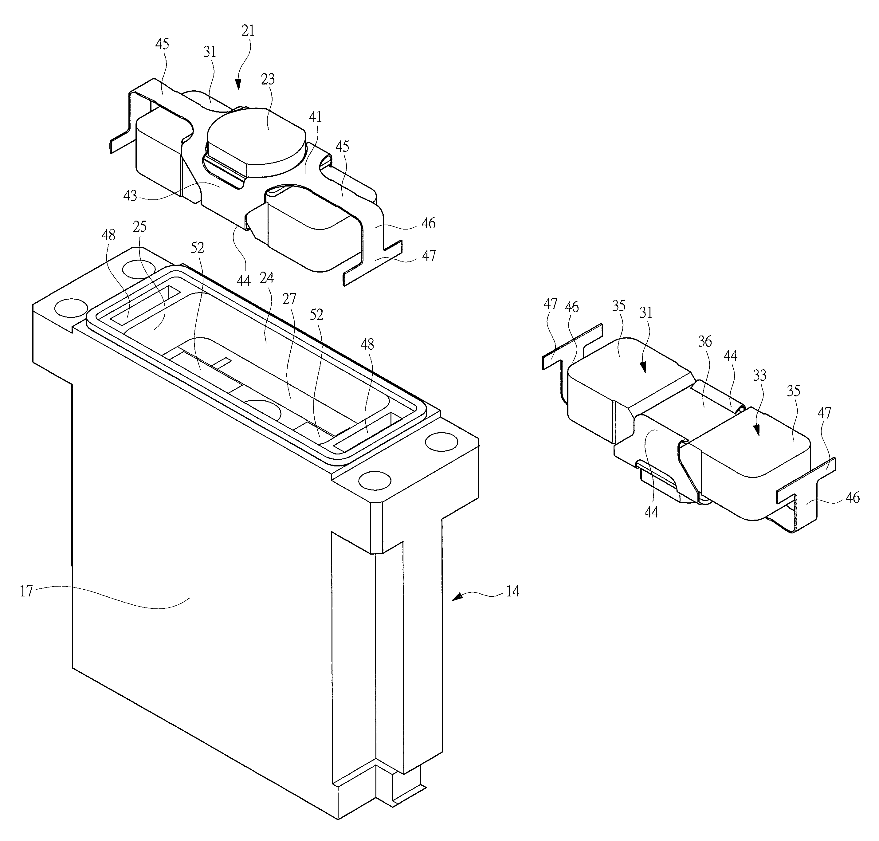
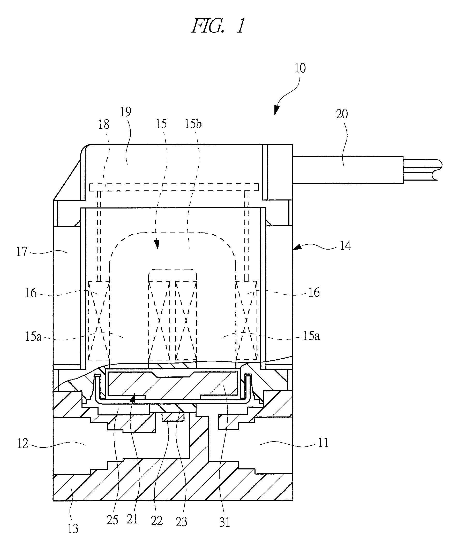
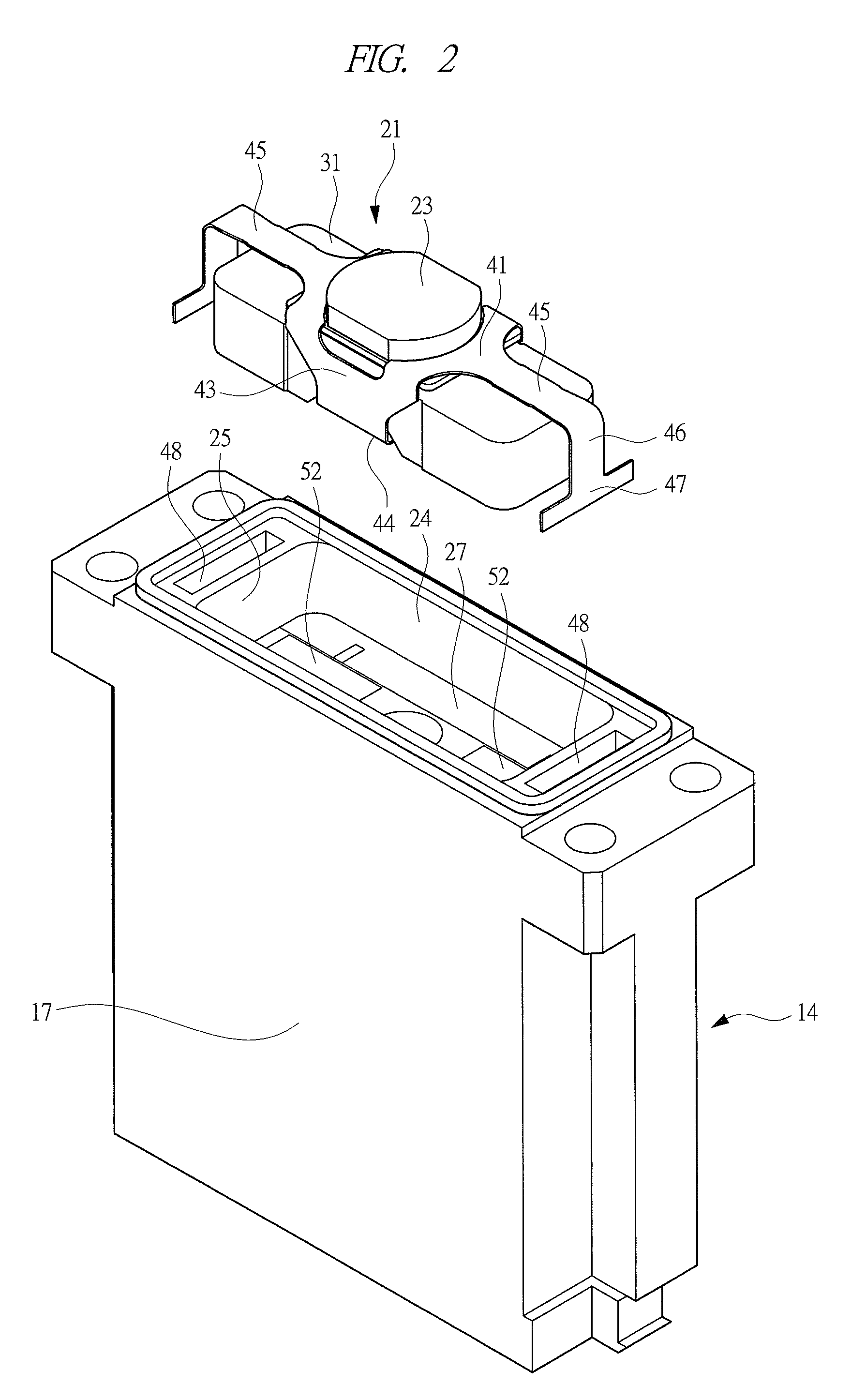
[0021]Hereinafter, embodiments of the present invention will be described in detail on the basis of the drawings. As shown in FIG. 1, a solenoid valve 10 has a valve body 13 in which an inflow port 11 and an outflow port 12 are formed. This solenoid valve 10 is a directional control valve for opening and closing a flow channel which makes the inflow port 11 and outflow port 12 communicate with each other, so as to be switched between a state where gas is supplied from the inflow port 11 to the outflow port 12 and a state where gas is not supplied.

[0022]A solenoid 14 is attached to the block-shaped valve body 13 formed with the ports, and the solenoid 14 has a fixed iron core 15 and a coil 16, and these are incorporated in a resin case 17. This case 17 is formed by a metallic mold for resin molding with the fixed iron core 15 and the coil 16 being incorporated in it. The fixed iron core 15 is provided with two parallel portions 15a extending in parallel with each other and a connecti...


PUM


Abstract

A solenoid is operated so as to be switched between a closed valve state in which the valve element is brought into contact with the valve seat by application of a spring force and an open valve state in which an electric current is passed through a coil (16) and the valve element is separated from the valve seat by a magnetic force. A fixed iron core (15) has a U-shape, and magnetically-attracting surfaces (26) are provided on respective ends thereof. A resin case (17) into which the fixed iron core (15) and the coil (16) are incorporated is provided with a bottom surface (27) having openings through which the magnetically-attracting surfaces (26) are exposed to the outside. A case contact surface (51) protruding toward a movable element in comparison with the magnetically-attracting surfaces (26) is formed on the bottom surface (27) of the case (17). Resin films (52) are provided on the respective magnetically-attracting surfaces (26).

Description

TECHNICAL FIELD[0001]The present invention relates to a solenoid valve for operating a valve element by a solenoid.BACKGROUND ART[0002]As one example of a solenoid valve for operating a valve element by a solenoid, a directional control valve for controlling an air flowing direction is known. As this directional control valve, an opening / closing valve for opening and closing a flow channel by the valve element, a switching valve for switching a flow channel, and the like are known. Supply and interruption of supplying of compressed air to a pneumatic circuit are controlled by the opening and closing valve, and a supplying direction of the compressed air is controlled by the switching valve. The solenoid valve has an electromagnet, i.e., a solenoid incorporated in a resin case and provided with a fixed iron core and a coil wound on the fixed iron core, and a valve body in which a movable element, i.e., an armature operating a valve element is incorporated, and the movable element is ...

Claims


Application Information

Patent Timeline
Patent Type & Authority Patents(United States)
IPC IPC(8): F01L3/10F16K31/72F16K31/06
CPCF16K31/0679F16K31/0655
Inventor TSUCHIZAWA, TOSHIAKI
Owner KOGANEI
Why Eureka
Try Eureka