Downhole safety valve apparatus and method

a safety valve and subsurface technology, applied in the direction of fluid removal, sealing/packing, borehole/well accessories, etc., can solve the problems of existing subsurface safety valves being stuck or otherwise inoperable, affecting the safety of subsurface safety valves, and causing dangerous surface blowouts

Active Publication Date: 2009-12-29
BAKER HUGHES INC
View PDF7 Cites 47 Cited by
  • Summary
  • Abstract
  • Description
  • Claims
  • Application Information

AI Technical Summary

Problems solved by technology

Absent safety valves, sudden increases in downhole pressure can lead to catastrophic blowouts of production and other fluids into the atmosphere.
An existing subsurface safety valve can become stuck or otherwise inoperable either through failure of various safety valve components or because of caked-up hydrocarbon deposits, for example.
In these circumstance, sudden increases in production zone pressure can lead to dangerous surface blowouts if the safety valves are not repaired.
Because the repair or replacement of a subsurface safety valve formerly required the removal of the string of production tubing from the wellbore, these operations were frequently prohibitively costly for marginal wells.

Method used


Image

  • Downhole safety valve apparatus and method
  • Downhole safety valve apparatus and method

Examples


Embodiment Construction

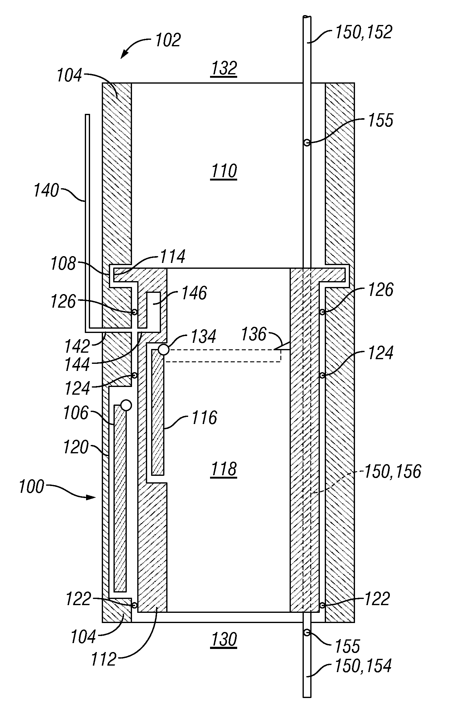
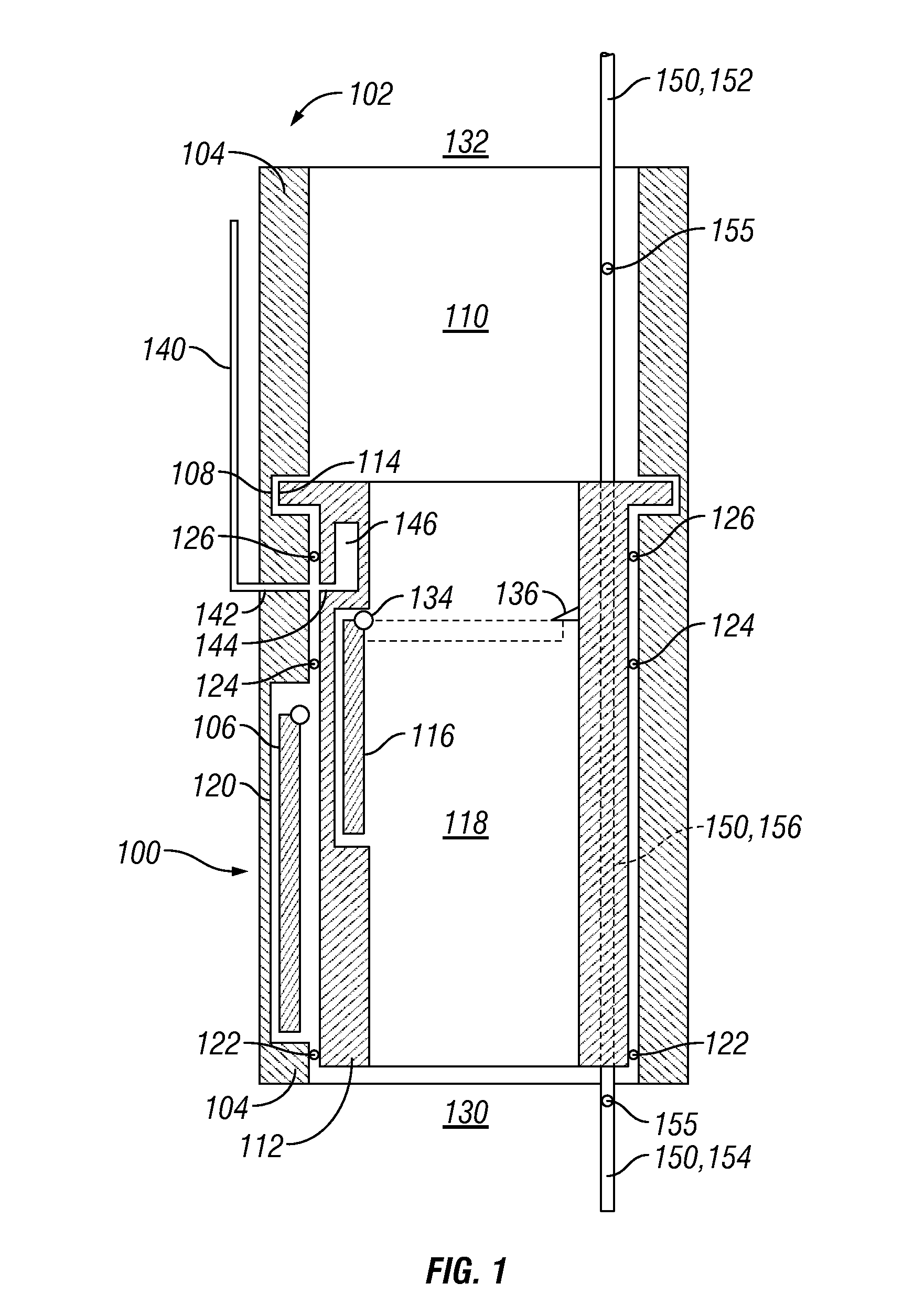
[0019]Referring initially to FIG. 1, a schematic representation of a replacement subsurface safety valve assembly 100 is shown engaged within an existing subsurface safety valve 102. Existing safety valve 102 includes a generally tubular valve body 104, a flapper 106, a landing profile 108, and a clearance bore 110. Likewise, replacement valve assembly 100 includes a main body 112, an engagement profile 114, a flapper 116, and a clearance bore 118.

[0020]With a replacement safety valve desired to be located within an existing safety valve 102, replacement valve assembly 100 is disposed downhole through the string of tubing or borehole where preexisting safety valve 102 resides. Once replacement valve 100 reaches existing safety valve 102, replacement valve 100 is actuated through clearance bore 110 until engagement profile 114 of replacement valve 100 engages and locks within landing profile 108 of existing safety valve 102. Landing and engagement profiles 108, 114 are shown schemati...


PUM


Abstract

A safety valve (100) replaces an existing safety valve (102) in order to isolate a production zone from a tubing string when closed. Preferably the safety valve (100) includes a flow interruption device (106) displaced by an operating conduit extending from a surface location to the safety valve (100) through the inside of the production tubing. A by-pass conduit (150) allows communication from a surface location to the production zone through the safety valve (100) without affecting the operation of the safety valve (100).

Description

CROSS-REFERENCE TO RELATED APPLICATION[0001]This application claims the benefit of provisional application U.S. Ser. No. 60 / 522,500 filed Oct. 7, 2004.BACKGROUND OF THE INVENTION[0002]The present invention generally relates to subsurface safety valves. More particularly, the present invention relates to an apparatus and method to install a replacement safety valve to a location where a previously installed safety valve is desired to be replaced. More particularly still, the present invention relates to communicating with a production zone through a bypass-conduit when a replacement safety valve is closed.[0003]Subsurface safety valves are typically installed in strings of tubing deployed to subterranean wellbores to prevent the escape of fluids from one production zone to another. Absent safety valves, sudden increases in downhole pressure can lead to catastrophic blowouts of production and other fluids into the atmosphere. For this reason, drilling and production regulations throug...

Claims


Application Information

Patent Timeline
Patent Type & Authority Patents(United States)
IPC IPC(8): E21B34/10
CPCE21B43/25E21B34/106
Inventor BOLDING, JEFFREY L.SMITH, DAVID R
Owner BAKER HUGHES INC
Why Eureka
Try Eureka