Joint device for artificial leg, method of controlling the joint device, and control unit

a joint device and artificial leg technology, applied in the field of joint device for artificial legs, a control unit, and a control unit, can solve the problems of user falling, device is not capable of actively moving the foot member and the under-knee member, and inability to perform,

Inactive Publication Date: 2010-01-05
HONDA MOTOR CO LTD
View PDF5 Cites 109 Cited by
  • Summary
  • Abstract
  • Description
  • Claims
  • Application Information

AI Technical Summary

Benefits of technology

[0039]According to this method of controlling a joint device for an artificial leg, the same advantageous effects as provided by the first embodiment of the present invention can be obtained.
[0040]Preferably, the release step includes controlling the actuator in respect of at least one of an operational speed and an operational timing.
[0041]More preferably, the actuator comprises a plurality of actuators connected to different locations on the upper member and the lower member, and the release step includes controlling the actuators such that the actuators operate differently in respect of at least one of the operational speed and the operational timing, so as to cause the joint motion in a direction different from a direction in which the weight of the user's body acts.
[0042]For example, the upper member is an above-knee member, and the lower member is an under-knee member.
[0043]For example, the upper member is an under-knee member, and the lower member is a foot member.
[0044]More preferably, the actuator comprises a plurality of actuators connected to different locations on the upper member and the lower member, the lower member being rotatably connected to the actuators, and the release step includes controlling the actuators such that the actuators operate differently in respect of at least one of the operational speed and the operational timing, so as to cause rotational motion including twisting motion, as the joint motion.

Problems solved by technology

However, the above joint device is not capable of moving the foot member and the under-knee member actively, but the foot member and the under-knee leg portion just passively perform pivotal motion with respect to each other depending on a reaction force generated e.g. by landing of the foot member.
If the user fails to perform toe-up motion, the toe of the foot member is easily caught e.g. at an uneven spot on a road, which can cause a fall of the user in the worst case.
On the other hand, inability to perform kicking motion cannot lead to a fall of the user, but when the user is walking on an unpaved road, no dust is raised, which reveals the use of the artificial leg.
This inflicts such a big pain on the user of the artificial leg as non-handicapped people cannot imagine.
However, this joint device suffers from other problems, such as a short duration of power supply and an increased weight.
Further, although the above-mentioned conventional joint device has the function of swinging the under-knee member forward by utilizing a centrifugal force, triggering motion for causing the swinging motion is troublesome, which makes it difficult to perform “knee bending / stretching motion” (see FIGS. 27B to 27D).
This swinging-out motion immediately reveals the use of the artificial leg, which is most painful to the user of the artificial leg.

Method used


Image

  • Joint device for artificial leg, method of controlling the joint device, and control unit
  • Joint device for artificial leg, method of controlling the joint device, and control unit
  • Joint device for artificial leg, method of controlling the joint device, and control unit

Examples


Embodiment Construction

[0105]The invention will now be described in detail with reference to drawings showing preferred embodiments thereof.

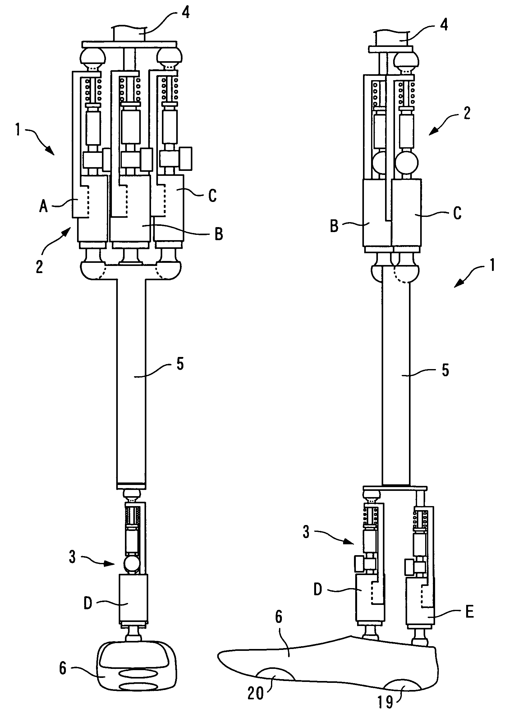
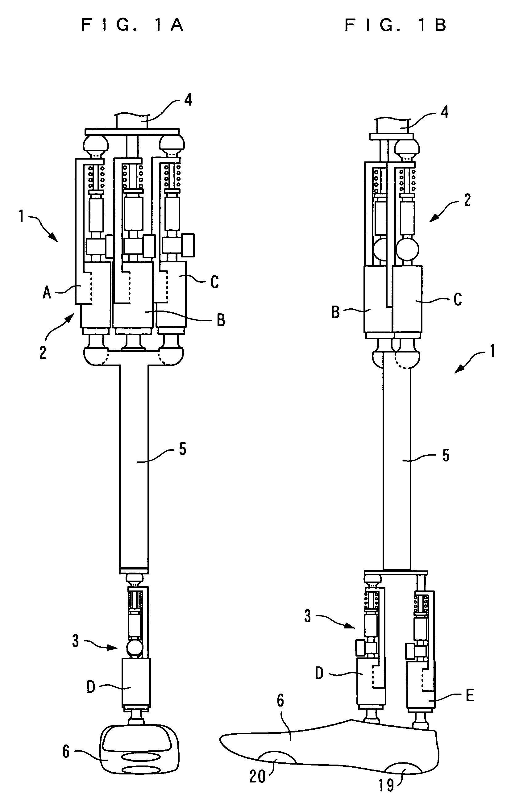
[0106]Referring first to FIGS. 1A, 1B, there is shown the whole arrangement of an artificial leg according to a first embodiment of the invention. The artificial leg 1 is a combination of a knee joint device 2 and an ankle joint device 3. The knee joint device 2 is comprised of an above-knee member 4 as an upper member attached to a hip joint, not shown, three expansible links A, B, C as actuators connected to the lower side of the above-knee member 4, and an under-knee member 5 as a lower member connected to the respective lower sides of the expansible links A, B, C. Further, the ankle joint device 3 is comprised of the under-knee member 5, two expansible links D, E connected to the lower side of the under-knee member 5, and a foot member 6 connected to the respective lower sides of the expansible links D, E.

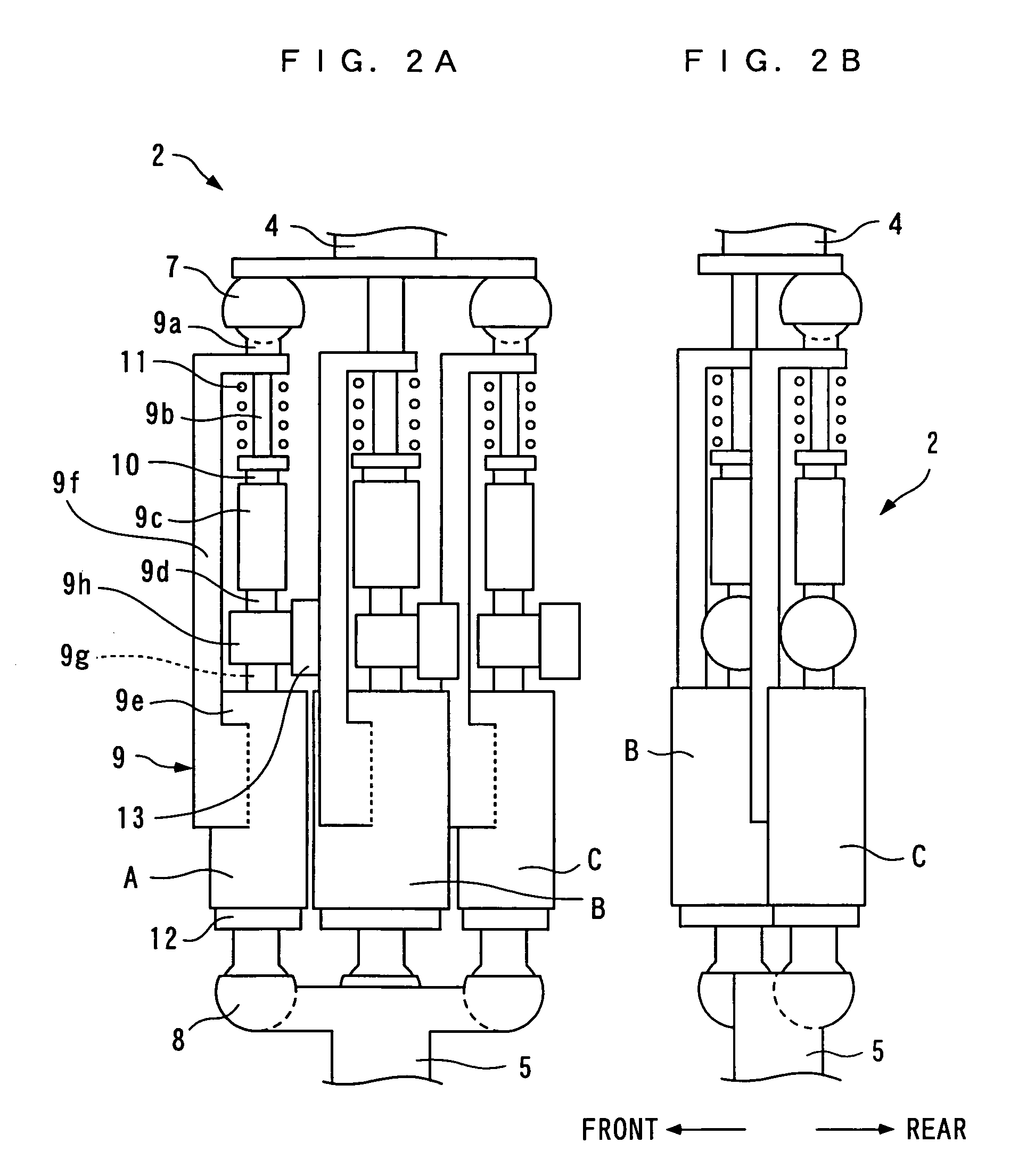
[0107]As shown in FIGS. 2A, 2B, the expansible links (herei...


PUM


Abstract

There is provided a joint device for an artificial leg, which makes it possible to dramatically achieve reduction of the weight of a power source and an increase in duration of the same, as well as facilitates knee bending / stretching motion, toe-up motion, and kicking motion. The joint device has an above-knee member and an under-knee member spaced from each other. Three expansible links are connected between the above-knee member and the under-knee member, for accumulating energy generated by the weight of a user's body acting on the artificial leg, and operating by releasing the accumulated energy to actuate the under-knee member into joint motion.

Description

RELATED APPLICATION[0001]This application is a 35 U.S.C. 371 national stage filing of International Application No. PCT / JP2003 / 010810, filed 26 Aug. 2003, which claims priority to Japanese Patent Application No. 2002-253280 filed on 30 Aug. 2002 in Japan. The contents of the aforementioned applications are hereby incorporated by reference.TECHNICAL FIELD[0002]This invention relates to a joint device for an artificial leg, a method of controlling the joint device, and a control unit.BACKGROUND ART[0003]Conventionally, a joint device for an artificial leg has been disclosed e.g. in Japanese Laid-Open Patent Publication (Kokai) No. 11-345. The joint device is applied to an ankle joint for connecting between a foot member of an artificial leg and an under-knee member of the same. The foot member of the artificial leg has an upper end portion thereof formed with a through hole extending laterally. On the other hand, the under-knee member has a lower end thereof bifurcated into two arms t...

Claims


Application Information

Patent Timeline
Patent Type & Authority Patents(United States)
IPC IPC(8): A61F2/64A61F2/48A61F2/62A61F2/50A61F2/60A61F2/66A61F2/68A61F2/70A61F2/74A61F2/76
CPCA61F2/60A61F2/64A61F2/642A61F2/6607A61F2/68A61F2002/5066A61F2002/5093A61F2002/701A61F2002/704A61F2002/741A61F2002/745A61F2002/748A61F2002/7615A61F2002/7625A61F2002/7635A61F2002/7685A61F2/70A61F2/74A61F2/741A61F2/748
Inventor YASUI, YUJI
Owner HONDA MOTOR CO LTD
Why Eureka
Try Eureka