Multilayer capacitor

a multi-layer capacitor and capacitor technology, applied in the field of multi-layer capacitors, to achieve the effect of lowering the equivalent series inductance, and shortening the length of the conduction path

Active Publication Date: 2010-01-26
TDK CORPARATION
View PDF18 Cites 3 Cited by
  • Summary
  • Abstract
  • Description
  • Claims
  • Application Information

AI Technical Summary

Benefits of technology

[0006]For solving the problem mentioned above, it is an object of the present invention to provide a multilayer capacitor which can further lower the equivalent series inductance.
[0028]The present invention can provide a multilayer capacitor which can further lower the equivalent series inductance.

Problems solved by technology

However, the multilayer capacitor described in Japanese Patent Application Laid-Open No. 2002-299152 cannot further lower the equivalent series inductance, which makes it necessary to further lower the equivalent series inductance in order to respond to circuits with a higher frequency.

Method used


Image

  • Multilayer capacitor
  • Multilayer capacitor
  • Multilayer capacitor

Examples


first embodiment

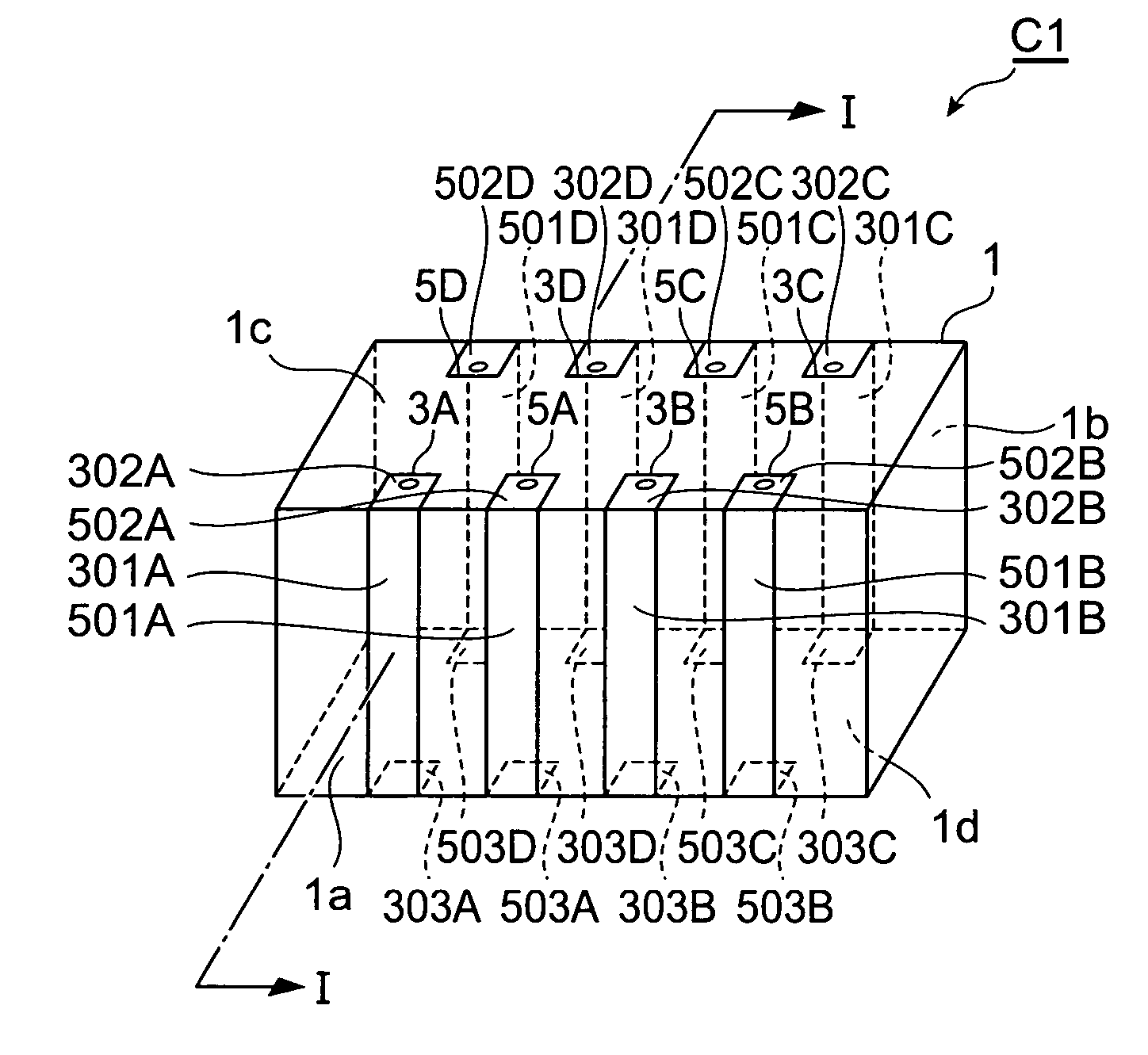
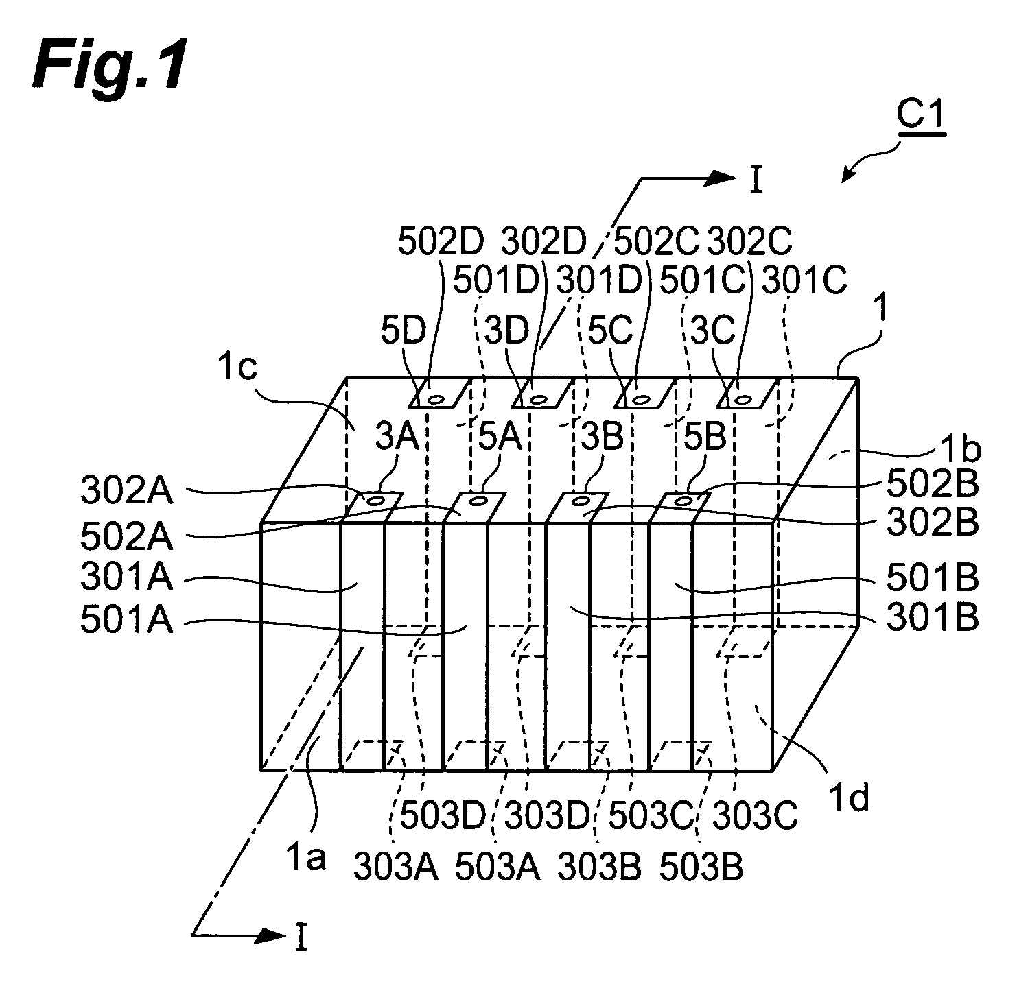
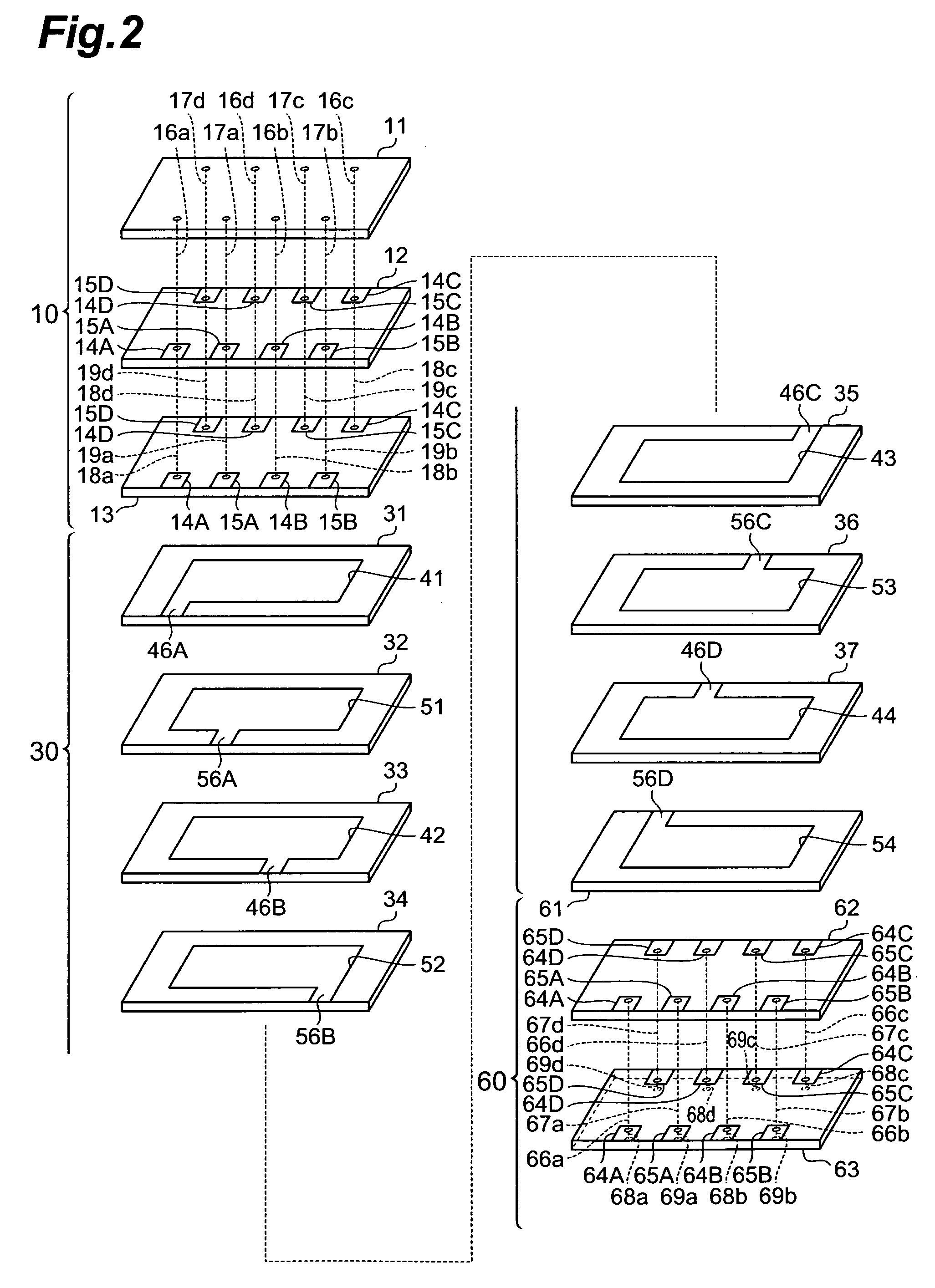
[0058]With reference to FIGS. 1 and 2, the structure of the multilayer capacitor C1 in accordance with a first embodiment will be explained. FIG. 1 is a perspective view of the multilayer body included in the multilayer capacitor C1 in accordance with the first embodiment. FIG. 2 is an exploded perspective view of the multilayer body included in the multilayer capacitor in accordance with the first embodiment.

[0059]As shown in FIG. 1, the multilayer capacitor C1 comprises a multilayer body 1 including an inner layer portion 30 and outer layer portions 10, 60; a plurality of (4 in this embodiment) first terminal electrodes 3A to 3D formed on the multilayer body 1; and a plurality of (4 in this embodiment) second terminal electrodes 5A to 5D similarly formed on the multilayer body 1.

[0060]The first terminal electrodes 3A, 3B and second terminal electrodes 5A, 5B are positioned on a side face 1a of the multilayer body 1. The first terminal electrodes 3C, 3D and second terminal electrod...

second embodiment

[0157]With reference to FIG. 6, the structure of the multilayer capacitor in accordance with a second embodiment will be explained. The multilayer capacitor in accordance with the second embodiment differs from the multilayer capacitor C1 in accordance with the first embodiment in that inner electrodes are connected to each of a plurality of terminal electrodes through lead conductors. FIG. 6 is an exploded perspective view of the multilayer body included in the multilayer capacitor in accordance with the second embodiment.

[0158]As with the multilayer capacitor C1 in accordance with the first embodiment, the multilayer capacitor in accordance with the second embodiment comprises a multilayer body 1, first terminal electrodes 3A to 3D formed on the multilayer body 1, and second terminal electrodes 5A to 5D similarly formed on the multilayer body 1, which are not depicted. The terminal electrodes 3A to 3D, 5A to 5D include first terminal conductor portions 301A to 301D, 501A to 501D, ...

third embodiment

[0188]With reference to FIGS. 8 and 9, the structure of the multilayer capacitor C2 in accordance with a third embodiment will be explained. The multilayer capacitor C2 in accordance with the third embodiment differs from the multilayer capacitor C1 in accordance with the first embodiment in terms of the number of first and second terminal electrodes. FIG. 8 is a perspective view of the multilayer capacitor in accordance with the third embodiment. FIG. 9 is an exploded perspective view of the multilayer body included in the multilayer capacitor in accordance with the third embodiment.

[0189]As shown in FIG. 8, the multilayer capacitor C2 comprises a multilayer body 1 including an inner layer portion 30 and outer layer portions 10, 60, a plurality of (5 in this embodiment) first terminal electrodes 3A to 3E formed on the multilayer body 1, and a plurality of (5 in this embodiment) second terminal electrodes 5A to 5E formed on the multilayer body 1.

[0190]The first terminal electrodes 3...


PUM


Abstract

A multilayer capacitor comprises a multilayer body and a plurality of terminal electrodes formed on a side face of the multilayer body. The multilayer body includes an inner layer portion in which a plurality of dielectric layers and a plurality of inner electrodes are alternately laminated, and an outer layer portion in which a plurality of dielectric layers are laminated. In the outer layer portion, a conduction path electrically connecting a plurality of different positions in at least one of the plurality of terminal electrodes to each other is arranged. A current flowing through the terminal electrode electrically connected to the conduction path is shunted into the conduction path. This lowers the equivalent series inductance of the multilayer capacitor.

Description

BACKGROUND OF THE INVENTION[0001]1. Field of the Invention[0002]The present invention relates to a multilayer capacitor.[0003]2. Related Background Art[0004]Recently, as power circuits used in electronic devices have been attaining higher frequencies, multilayer capacitors employed in the power circuits have further been demanded to conform to high-frequency circuits. For realizing low impedance in high-frequency circuits as well, it has been required for multilayer capacitors to lower their equivalent series inductance (ESL). For responding to such a request, Japanese Patent Application Laid-Open No. 2002-299152 discloses a multilayer capacitor which arranges a plurality of terminal electrodes such that those adjacent to each other have polarities opposite to each other, so that magnetic fields generated thereby cancel each other out, thereby lowering the equivalent series inductance.SUMMARY OF THE INVENTION[0005]However, the multilayer capacitor described in Japanese Patent Applic...

Claims


Application Information

Patent Timeline
Patent Type & Authority Patents(United States)
IPC IPC(8): H01G4/228
CPCH01G4/012H01G4/30H01G4/232
Inventor TOGASHI, MASAAKI
Owner TDK CORPARATION
Why Eureka
Try Eureka