Multilayer capacitor

a multi-layer capacitor and capacitor technology, applied in the field of multi-layer capacitors, can solve the problem of difficult to achieve low impedance over a wide frequency band, and achieve the effect of lowering the equivalent series inductance of the multi-layer capacitor, and shortening the current path

Active Publication Date: 2011-08-09
TDK CORPARATION
View PDF11 Cites 6 Cited by
  • Summary
  • Abstract
  • Description
  • Claims
  • Application Information

AI Technical Summary

Benefits of technology

[0006]It is an object of the present invention to provide a multilayer capacitor which can attain low impedance over a wide frequency band.
[0008]In this multilayer capacitor, the first and second terminal electrodes are formed on longitudinally extending side faces of the capacitor body having a rectangular parallelepiped form. This can shorten current paths through the first and second inner electrodes, thereby lowering the equivalent series inductance of the multilayer capacitor. In the first inner electrode, the first and second main electrode portions contributing to forming the capacitance are arranged as wide as the first lead electrode portion in the opposing direction of the first and second end faces. This can further shorten the current path through the first inner electrode. In the second inner electrode, the third and fourth main electrode portions contributing to forming the capacitance are arranged as wide as the second lead electrode portion in the opposing direction of the first and second end faces. This can further shorten the current path through the second inner electrode. They can also lower the equivalent series inductance of the multilayer capacitor. In this multilayer capacitor, the combined capacitance of a plurality of capacitance components connected in series and formed by the first and second inner electrodes and first intermediate electrode differs from that of a plurality of capacitance components connected in series and formed by the first and second inner electrodes and second intermediate electrode. Since these different combined capacitances are connected in parallel with each other, the multilayer capacitor can lower the impedance over a wide frequency band.
[0012]In this multilayer capacitor, the first and second terminal electrodes are formed on longitudinally extending side faces of the capacitor body having a rectangular parallelepiped form. This can shorten current paths through the first and second inner electrodes, thereby lowering the equivalent series inductance of the multilayer capacitor. In the first inner electrode, the first and second main electrode portions contributing to forming the capacitance are arranged as wide as the first lead electrode portion in the opposing direction of the first and second end faces. This can further shorten the current path through the first inner electrode. This can also lower the equivalent series inductance of the multilayer capacitor. In this multilayer capacitor, the capacitance formed by the first and third inner electrodes differs from the combined capacitance of a plurality of capacitance components connected in series and formed by the first and second inner electrodes and intermediate electrode. Since these different capacitances are connected in parallel with each other, the multilayer capacitor can lower the impedance over a wide frequency band.
[0013]Preferably, in the opposing direction of the first and second end faces, each of the second and third lead electrode portions has a length identical to that of the first lead electrode portion. This can further lower the equivalent series inductance.

Problems solved by technology

However, the multilayer capacitor disclosed in Japanese Patent Application Laid-Open No. 9-148174 has only one capacitor component and thus is hard to attain low impedance over a wide frequency band.

Method used


Image

  • Multilayer capacitor
  • Multilayer capacitor
  • Multilayer capacitor

Examples


first embodiment

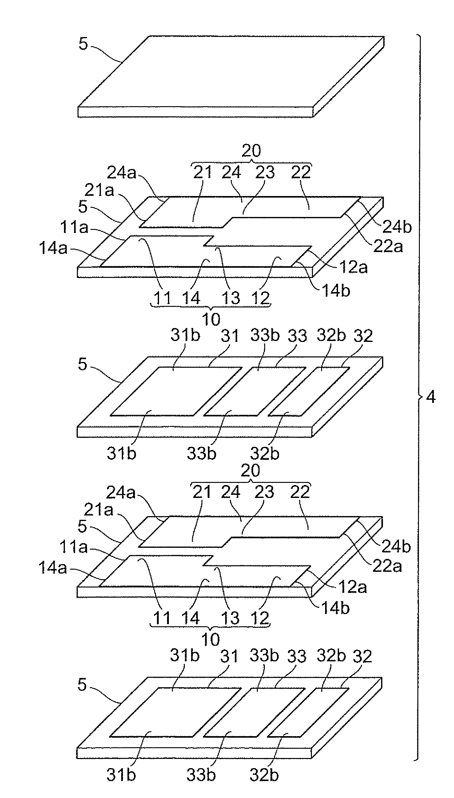
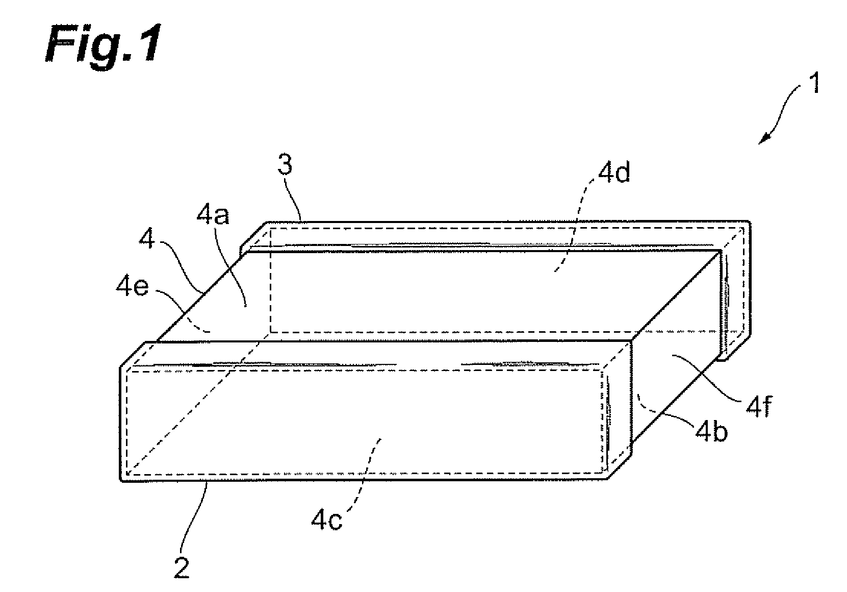
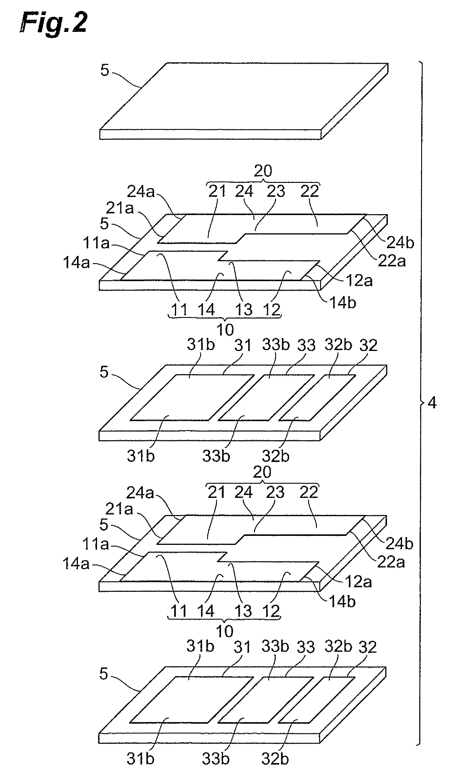
[0030]The structure of the multilayer capacitor 1 in accordance with the first embodiment will be explained with reference to FIGS. 1 to 4. FIG. 1 is a perspective view of the multilayer capacitor in accordance with this embodiment. FIG. 2 is an exploded perspective view of the capacitor body included in the multilayer capacitor in accordance with this embodiment. FIG. 3 is a view for explaining the opposing relationship between the inner and intermediate electrodes included in the capacitor body of the multilayer capacitor in accordance with this embodiment. FIG. 4 is an equivalent circuit diagram of the multilayer capacitor in accordance with this embodiment.

[0031]As shown in FIG. 1, the multilayer capacitor 1 comprises a capacitor body 4 having a rectangular parallelepiped form, and a first terminal electrode 2 and a second terminal electrode 3 which are arranged on outer surfaces of the capacitor body 4. As shown in FIG. 1, the capacitor body 4 has rectangular first and second m...

second embodiment

[0064]With reference to FIGS. 5 and 6, the structure of the multilayer capacitor in accordance with the second embodiment will be explained. The multilayer capacitor in accordance with the second embodiment differs from the multilayer capacitor in accordance with the first embodiment in terms of the number of intermediate electrodes. FIG. 5 is an exploded perspective view of the capacitor body included in the multilayer capacitor in accordance with the second embodiment. FIG. 6 is an equivalent circuit diagram of the multilayer capacitor in accordance with the second embodiment.

[0065]Though not depicted, the multilayer capacitor in accordance with the second embodiment comprises a capacitor body 4, a first terminal electrode 2, and a second terminal electrode 3 as with the multilayer capacitor 1 in accordance with the first embodiment. As shown in FIG. 5, the capacitor body 4 has a plurality of (5 in this embodiment) laminated dielectric layers 5.

[0066]As shown in FIG. 5, a pluralit...

third embodiment

[0096]With reference to FIGS. 7 to 9, the structure of the multilayer capacitor 41 in accordance with the third embodiment will be explained. FIG. 7 is a perspective view of the multilayer capacitor in accordance with this embodiment. FIG. 8 is an exploded perspective view of the capacitor body included in the multilayer capacitor in accordance with this embodiment. FIG. 9 is an equivalent circuit diagram of the multilayer capacitor in accordance with this embodiment.

[0097]As shown in FIG. 7, the multilayer capacitor 41 comprises a capacitor body 44 having a rectangular parallelepiped form, and a first terminal electrode 42 and a second terminal electrode 43 which are arranged on outer surfaces of the capacitor body 44. As shown in FIG. 7, the capacitor body 44 has rectangular first and second main faces 44a, 44b opposing each other, first and second side faces 44c, 44d extending in the longer side direction of the first and second main faces 44a, 44b so as to connect the first and ...


PUM


Abstract

A multilayer capacitor includes a capacitor body having rectangular first and second main faces opposing each other, first and second end faces extending in a shorter side direction of the first and second main faces so as to connect the first and second main faces to each other, and first and second side faces extending in a longer side direction of the first and second main faces so as to connect the first and second main faces to each other. First and second terminal electrodes are arranged on the first and second side faces of the capacitor body, respectively. A first inner electrode connected to the first terminal electrode, a second inner electrode connected to the second terminal electrode, and first and second intermediate electrodes connected to none of the first and second terminal electrodes are arranged within the capacitor body. The first intermediate electrode and first inner electrode form a combined capacitance different from that formed by the second intermediate electrode and second inner electrode.

Description

BACKGROUND OF THE INVENTION[0001]1. Field of the Invention[0002]The present invention relates to a multilayer capacitor.[0003]2. Related Background Art[0004]Known as this kind of multilayer capacitor is one comprising a rectangular parallelepiped capacitor body having a pair of opposing rectangular main faces, a pair of opposing side faces extending in a longer side direction of the pair of main faces so as to connect the pair of main faces to each other, and a pair of opposing end faces extending in a shorter side direction of the pair of main faces so as to connect the pair of main faces to each other; and a plurality of terminal electrodes arranged on the pair of side faces; wherein the capacitor body includes a plurality of insulator layers laminated in the opposing direction of the pair of main faces, and a plurality of inner electrodes arranged so as to oppose each other while holding therebetween at least one insulator layer in the plurality of insulator layers and connected ...

Claims


Application Information

Patent Timeline
Patent Type & Authority Patents(United States)
IPC IPC(8): H01G4/005H01G4/06H01G4/228
CPCH01G4/012H01G4/228H01G4/30
Inventor TOGASHI, MASAAKI
Owner TDK CORPARATION
Why Eureka
Try Eureka