
Mobile asphalt production machine

a production machine and asphalt technology, applied in the field of machines, can solve the problems of long life span and deterioration, material hardening, and inability to move easily or compact on the job site,

Inactive Publication Date: 2010-02-02
ZIMMERMAN HAROLD M
View PDF17 Cites 21 Cited by
  • Summary
  • Abstract
  • Description
  • Claims
  • Application Information

AI Technical Summary

Benefits of technology

The machine enables efficient, continuous production of large or small batches of bituminous concrete at the job site, minimizing temperature loss and allowing for on-site recycling, thus reducing repair costs and improving operational flexibility, especially in cold weather conditions.

Problems solved by technology

Very often, small repairs are done with cold-mix asphalt, which does not have a long life span and deteriorates quickly.
The central asphalt mixing plant is a fixed asset that cannot be easily moved from one location to another.
Once hot-mix asphalt is cooled, the material hardens and cannot be spread easily or compacted at the job site.
The shortness of time during which the bituminous concrete material remains pliable makes the material difficult to be utilized for small repair jobs, or for jobs that are a substantial distance from the central mixing plant.
Such problems are particularly difficult to overcome when the ambient temperatures are low, as will be found in the Northern states during the winter months.
This machine depicted in the '914 patent was expensive to manufacture and utilized a mixing drum that was rotated to mix and heat the aggregate for discharge into a mixing auger where the hot liquid bitumen was added to manufacture the bituminous concrete mixture.
While this arrangement was successful in mixing small patches of hot-mix bituminous concrete, the volume required for large repairs and / or re-surfacing projects could not be produced.
Furthermore, the machine disclosed in the '914 patent was not capable of recycling old bituminous concrete material.

Method used


Image

  • Mobile asphalt production machine
  • Mobile asphalt production machine
  • Mobile asphalt production machine

Examples


Embodiment Construction

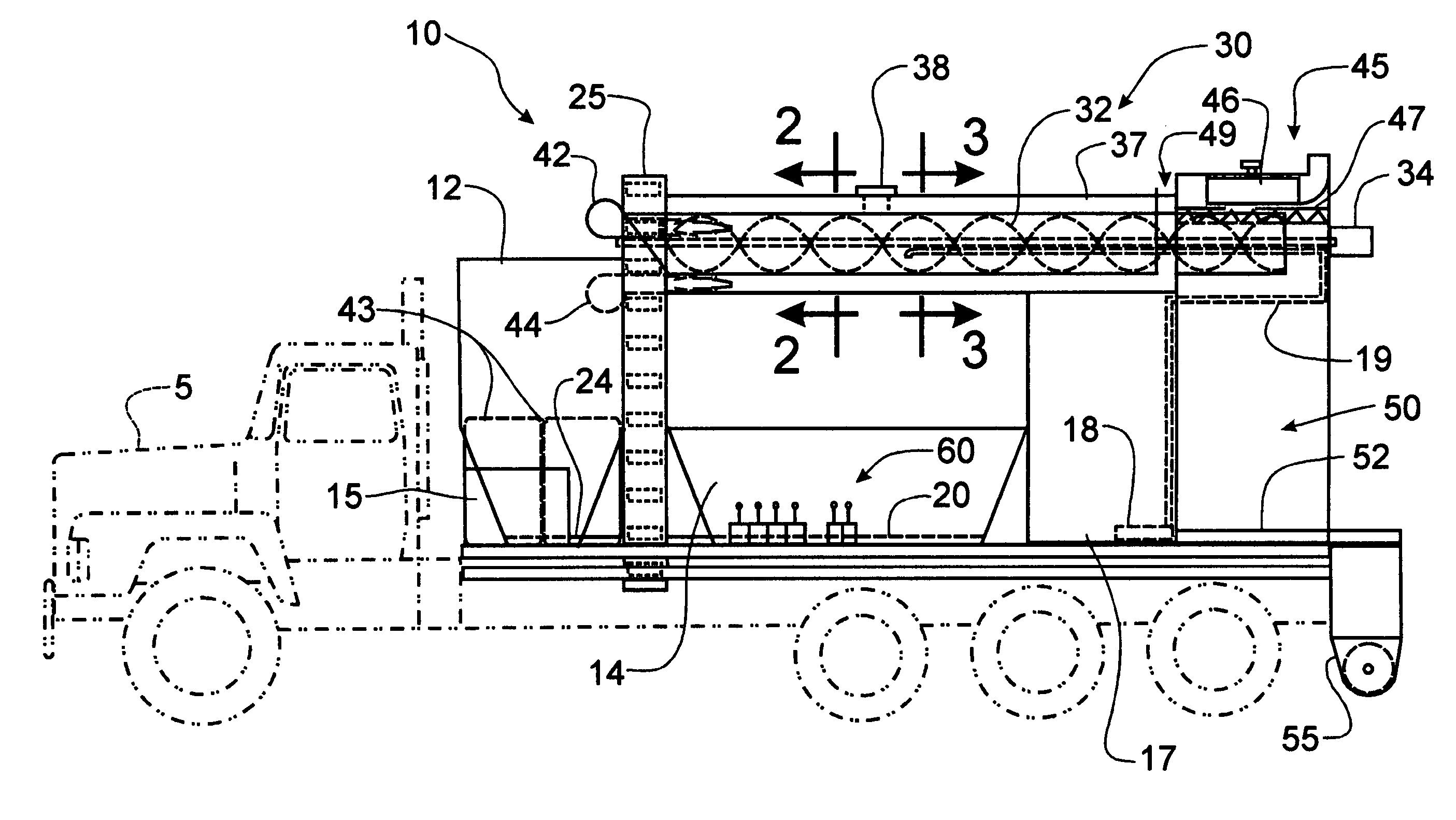
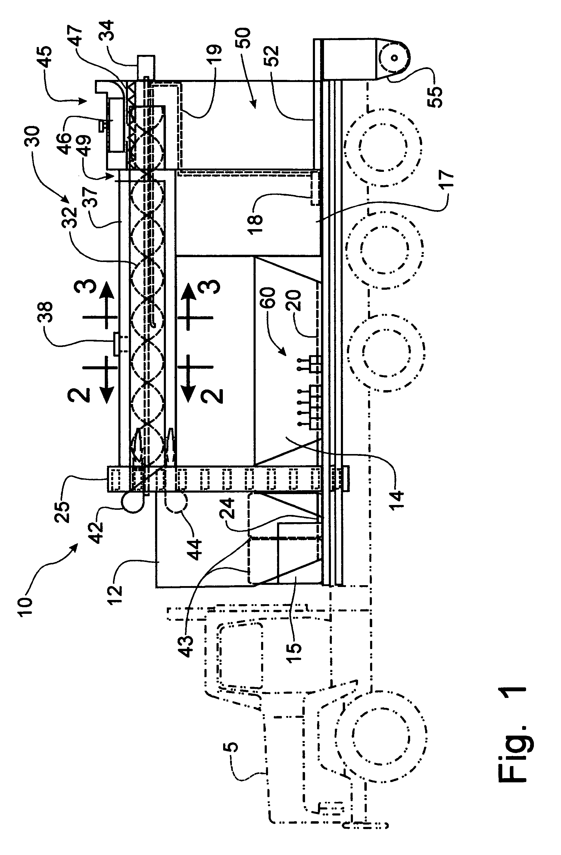
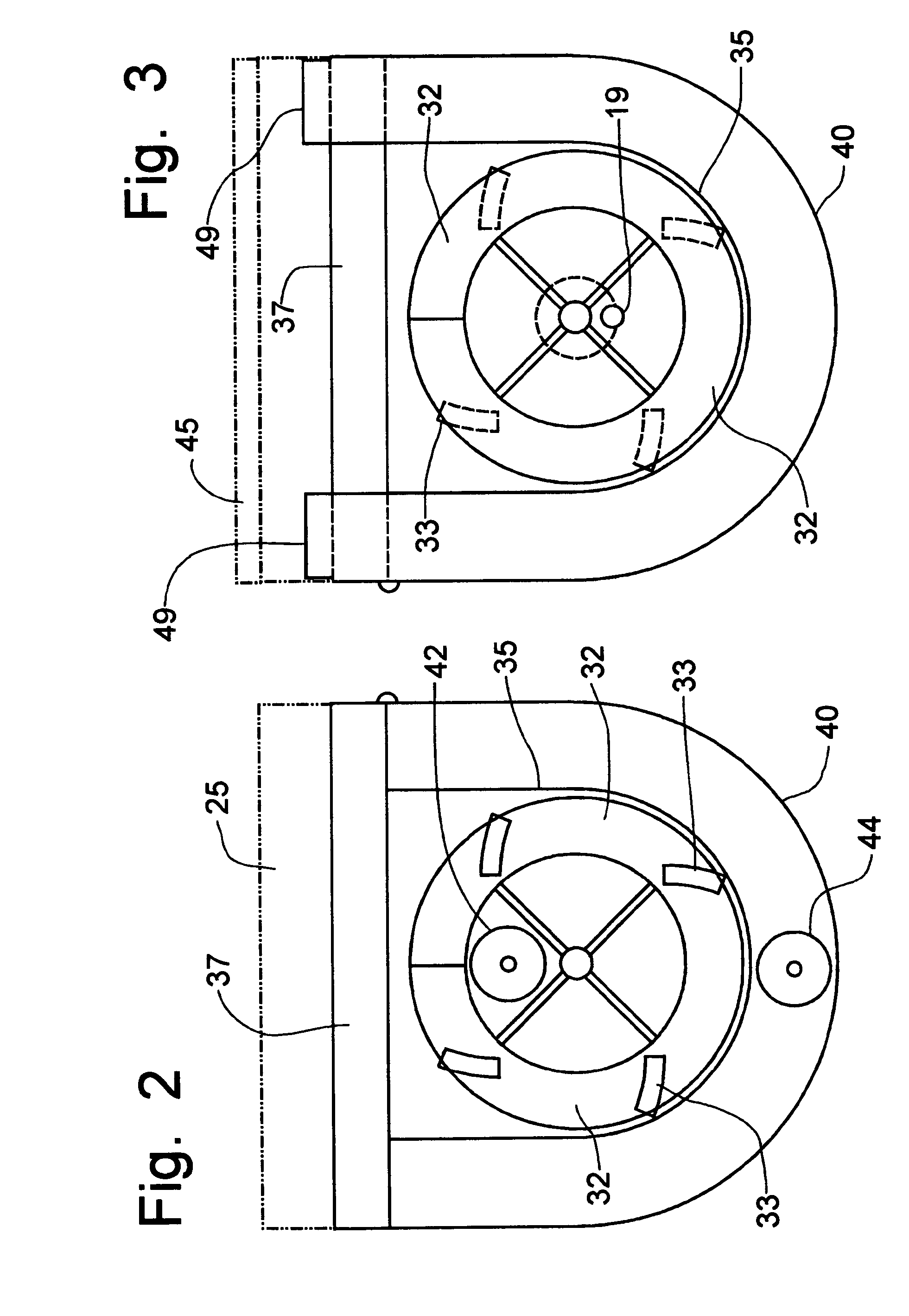
[0040]Referring to the FIGS. 1-7, a mobile asphalt production machine incorporating the principles of the instant invention can best be seen. The asphalt production machine 10 is mounted on a truck chassis 5, shown in phantom in FIG. 1, to provide mobility for the machine 10. The truck chassis 5 is preferably a tri-axle configuration, due to the weight of the machine 10 and of the aggregate and other components stored in the machine 10, as will be described in greater detail below. The truck chassis 5 includes a conventional engine and drive transmission (not shown) for affecting mobility of the machine 10. The arrangement is somewhat similar to the mobile concrete mixers of the type seen in U.S. Pat. No. 4,538,916, issued to Harold M. Zimmerman, on Sep. 3, 1985, which carry discrete quantities of the various materials and components used to produce Portland cement concrete. Such concrete mixing units have been marketed under the trademark ZIM-MIXER by Zimmerman Industries, Inc. of ...


PUM


Abstract

A mobile asphalt production machine mixes bituminous concrete at the job site through a mixing auger mechanism mounted in an insulated housing. Propane burners provide heat within the mixing auger mechanism and within the insulated housing to produce a hot-mix bituminous concrete in large or small batches. The components of the asphalt mixture are stored in separate bins that can be re-filled at the job site to provide a continuous supply of asphalt. Hot liquid bitumen is added to heated aggregate within the mixing auger mechanism. Recycled asphalt can be added through a port in the mixing auger for incorporation into the mixture. Controls permit the rate of flow of each individual component to be selectively varied in order to change the recipe for the mixture and to provide calibration of the component, while a master control will maintain the pre-established flow rates through a variable speed of operation.

Description

[0001]This application is a division of U.S. patent application Ser. No. 11 / 207,960, filed on Aug. 22, 2005, and entitled “Mobile Asphalt Production Machine”, issued as U.S. Pat. No. 7,458,746, on Dec. 2, 2008.BACKGROUND OF THE INVENTION[0002]The present invention is directed to machines that pave roads and, more particularly, to a self-contained mobile vehicle that is operable to create hot-mix bituminous concrete, asphalt, at the job site.[0003]Roadways are typically formed with either a Portland cement concrete roadway or a roadway formed from bituminous concrete, which is often referred as asphalt. When the roadway surfaces deteriorate, the repair thereto is typically done with an asphalt patch, even the Portland cement concrete road surfaces. Very often, small repairs are done with cold-mix asphalt, which does not have a long life span and deteriorates quickly. Large repairs, even complete re-surfacing of the roadway, are accomplished with large paving machines that receive sup...

Claims


Application Information

Patent Timeline
Patent Type & Authority Patents(United States)
IPC IPC(8): E01C19/12
CPCE01C19/1054E01C19/46E01C23/06
Inventor ZIMMERMAN, HAROLD M.
Owner ZIMMERMAN HAROLD M
Learn More