Method of manufacturing a handle for a beverage dispensing head

a beverage and handle technology, applied in the direction of food shaping, liquid transfer devices, other domestic articles, etc., can solve the problems of increasing machine time and overall cost, time-consuming and relatively expensive machining process, and general disadvantages of general machining process, so as to reduce the time and per unit cost of production

Inactive Publication Date: 2010-02-09
TAPRITE FASSCO MFG INC
View PDF3 Cites 38 Cited by
  • Summary
  • Abstract
  • Description
  • Claims
  • Application Information

AI Technical Summary

Benefits of technology

[0010]It is therefore an object of the present invention to provide a method of manufacturing a handle for a beverage dispensing head through the mass production technique of injection molding, whereby injection molding handle sections lowers the time and per unit cost of producing the handle as compared to the standard method of machining handle sections.

Problems solved by technology

While machining each section individually and assembling the sections into a handle produces handles suitable for use in beverage dispensing heads, the machining process in general suffers disadvantages.
In particular, the machining process is time-consuming and relatively expensive because each section is machined individually through a multi-step process, and each step increases both machine time and overall cost.
Moreover, a single section for one handle requires the same amount of time and labor to manufacture as the same section for another handle.
Furthermore, the tolerances that must be maintained to ensure the sections fit properly increase costs as well.
For example, the heat generated from the drilling of a channel or hole in a machined section can alter the size and shape of a component for a drilling device, thereby affecting the dimensions of the channel or hole created.
Vibrations from motors can cause parts on machining tools to move, which can change the position of where a section is cut.
In both examples, the result could be machined sections with holes and channels that do not align properly, rendering the sections useless.

Method used


Image

  • Method of manufacturing a handle for a beverage dispensing head
  • Method of manufacturing a handle for a beverage dispensing head
  • Method of manufacturing a handle for a beverage dispensing head

Examples


first embodiment

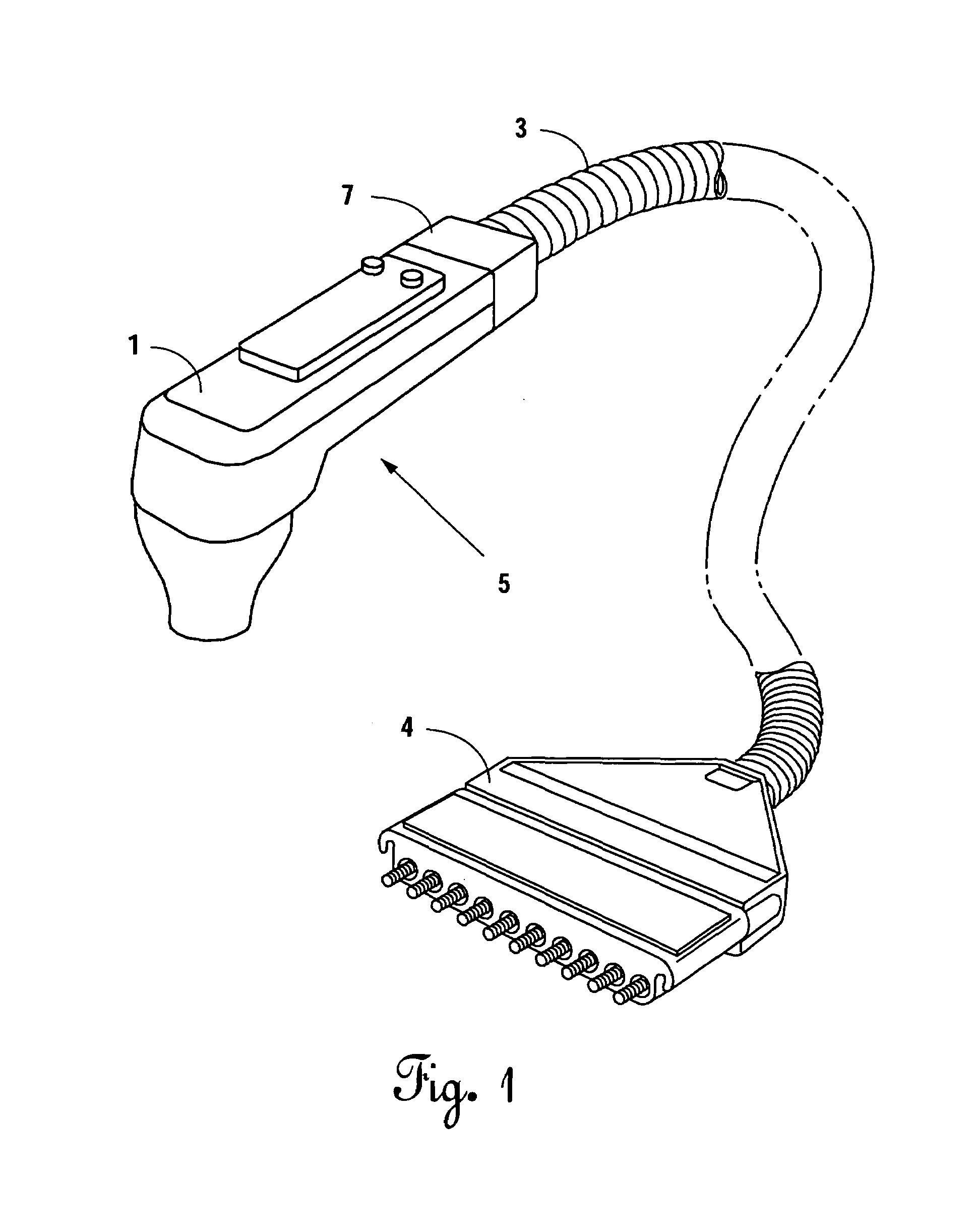
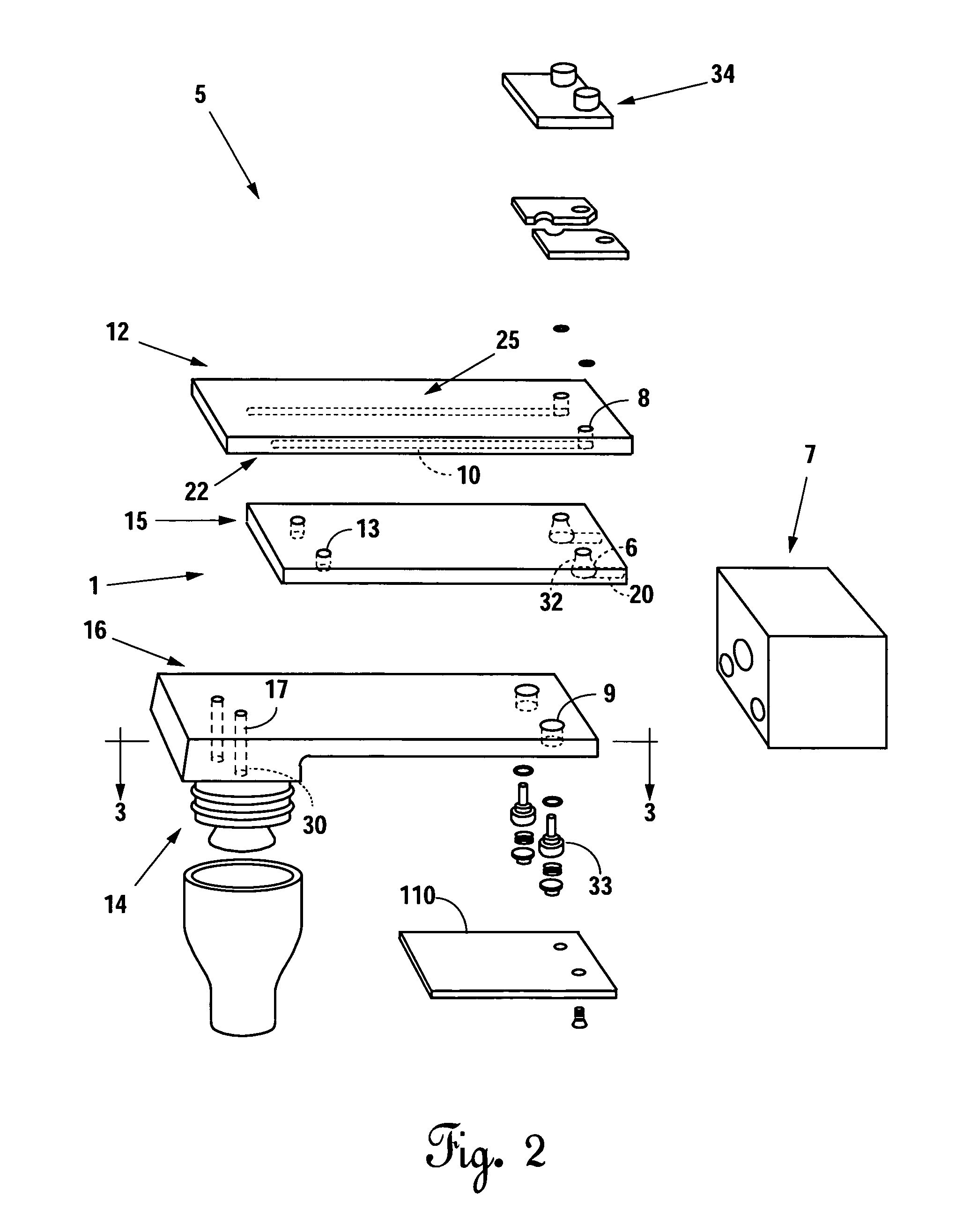
[0023]The beverage dispensing apparatus includes a beverage dispensing head 5, a brixing device 4, and a flexible line 3 including two hoses that couple the brixing device 4 to the beverage dispensing head 5. A beverage component source supplies the brixing device 4 with a base fluid and a mixing fluid, two base fluids, or two mixing fluids at elevated pressures.

[0024]The beverage dispensing head 5 includes a handle 1 with passageways 22 and 25 therethrough that communicate with a nozzle 14 secured to the handle 1. The beverage dispensing head 5 further includes and a retaining cap 7 that couples a first hose of the flexible line 3 with the passageway 22 and a second hose of the flexible line 3 with the passageway 25. The first hose supplies a base fluid or a mixing fluid from the brixing device 4 to the passageway 22, and the second hose supplies a base fluid or a mixing fluid from the brixing device 4 to the passageway 25. Each of the passageways 22 and 25 communicates the base f...

second embodiment

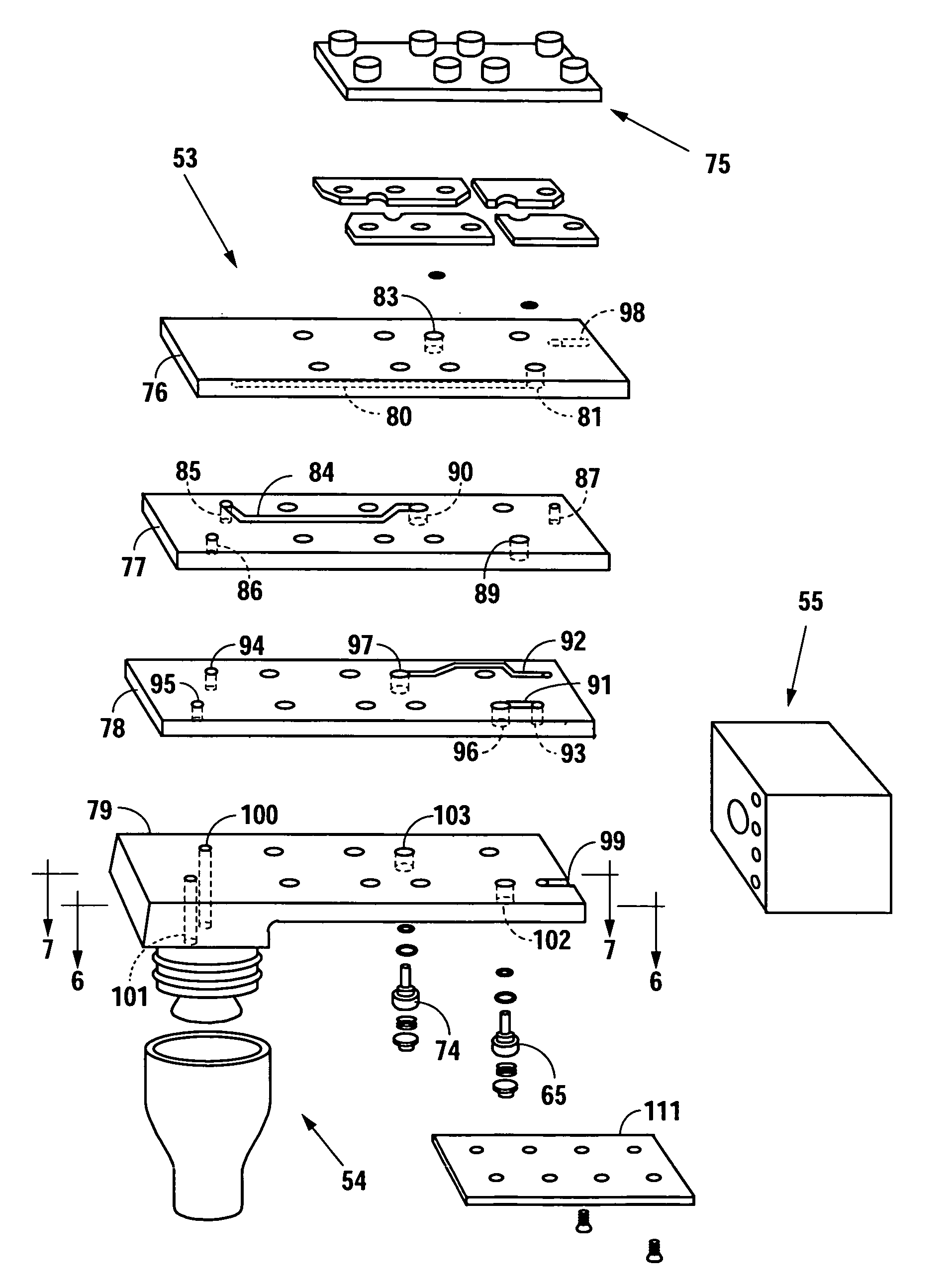
[0032]The beverage dispensing apparatus includes a beverage dispensing head 50, a brixing device 51, and a flexible line 52 including eight hoses that couple the brixing device 51 to the beverage dispensing head 50. A beverage component source supplies the brixing device 51 with eight base fluids, eight mixing fluids, or any combination of base and mixing fluids.

[0033]The beverage dispensing head 50 includes a handle 53 with eight passageways therethrough that communicate with a nozzle 54 frictionally secured to the handle 53 via o-rings. The beverage dispensing head 50 further includes and a retaining cap 55 that couples each of the eight hoses of the flexible line 52 with a respective passageway. Each of the hoses supplies a base fluid or a mixing fluid from the brixing device 51 to a respective passageway. Similarly, each passageway communicates the base fluid or the mixing fluid through the handle 53 and to the nozzle 54 which delivers the base fluid or mixing fluid from the be...


PUM

PropertyMeasurementUnit
flexibleaaaaaaaaaa
pressuresaaaaaaaaaa
transparentaaaaaaaaaa

Abstract

In a method of manufacturing a beverage dispensing head, a first section is molded to include an exit channel and a first portion of a valve bore. A second section is molded to include an entry channel, a passage through the second section, and a second portion of the valve bore. A third section is molded to include a passage through the third section and a third portion of the valve bore. The first section is mated with the second section and the second section is mated with the third section to form a handle including a passageway therethrough. The mating of the first section with the second section and the second section with the third section aligns the first portion with the second portion and the second portion with the third portion to form the valve bore for the passageway. In addition, the entry channel is sealed to form a fluid entry aperture and a fluid entry conduit for the passageway. Further, the exit channel is sealed to form a portion of a fluid exit conduit for the passageway. Still further, the exit channel aligns with the passages to form a portion of the fluid exit conduit and to provide a fluid exit aperture for the passageway. After forming the handle, a valve assembly is placed within the valve bore, and a valve actuator assembly is mounted onto the handle. A nozzle is secured to the handle such that the fluid exit aperture communicates with the nozzle.

Description

BACKGROUND OF THE INVENTION[0001]1. Field of the Invention[0002]The present invention relates to a beverage dispensing head, and, more particularly, but not by way of limitation, to a method of manufacturing a handle for a beverage dispensing head.[0003]2. Description of the Related Art[0004]A beverage dispensing apparatus typically termed a “bar gun” includes a beverage dispensing head and a brixing device coupled to the dispensing head through a flexible line having a plurality of hoses therein. A beverage component source supplies the brixing device with base fluids and mixing fluids at elevated pressures. Base fluids include beverage syrups, juices, wine, and liquor, while mixing fluids include plain and carbonated water.[0005]The beverage dispensing head includes a handle with a plurality of passageways therethrough whereby each hose within the flexible line connects with a passageway through a suitable retainer. Each passageway communicates either a base fluid or a mixing flui...

Claims


Application Information

Patent Timeline
Patent Type & Authority Patents(United States)
IPC IPC(8): B65D5/56B67D7/06
CPCB67D1/0084B67D1/1405Y10T29/49432Y10T29/49435B67D2210/0006
Inventor SCHROEDER, ALFRED A.
Owner TAPRITE FASSCO MFG INC
Why Eureka
Try Eureka