
Automatic functionality generating mechanism for network connecting appliances

a network connection and automatic technology, applied in the field of management and operation system of appliances, can solve the problems of insufficient router operation, high cost and time consumption, and insufficient connection of cables to appropriate terminals, and achieve the effect of automatically configuring the network connection applian

Active Publication Date: 2010-02-09
INTERNET INITIATIVE JAPAN
View PDF35 Cites 3 Cited by
  • Summary
  • Abstract
  • Description
  • Claims
  • Application Information

AI Technical Summary

Benefits of technology

[0013]According to the present invention, a system for managing a plurality of network connecting appliances is provided. The system according to the present invention includes first and second servers which can be connected to the plurality of network connecting appliances via a network; a first database which is connected to the first server and stores relationship between an identifier of each of the plurality of network connecting appliances and the second server responsible for the network connecting appliance; a second database which is connected to the second server and stores configuration data to be provided for each of the plurality of network connecting appliances such that the configuration data can be retrieved by using an identifier of the network connecting appliance; and a third database which is connected to the second server and stores function data to be provided for each of the plurality of network connecting appliances such that the function data can be retrieved by using an identifier of the network connecting appliance. Further, (a) each of the plurality of network connecting appliances includes: first storage means storing first connection data required for connecting to the first server; means for automatically sending an identifier of the network connecting appliance to the first server by using the first connection data stored in the first storage means in response to power being turned on; means for sending an identifier of the network connecting appliance to the second server by using a received second connection data when second connection data required for connecting to the second server which is responsible for the network connecting appliance, is received from the first server, means for automatically configuring the network connecting appliance by using the configuration data when the configuration data is received from the second server; and means for implementing a virtual function included in the function data as a physical function in the network connecting appliance by using the function data when the function data is received from the second server; (b) the first server includes; means for receiving an identifier from the plurality of network connecting appliances; meant for acquiring the second connection data required for connecting to the second server responsible for a network connecting appliance identified by using the received identifier from the first database; and means for sending the acquired second connection data to the network connecting appliance that has sent the identifier, and (c) the second server includes; means for receiving an identifier from the plurality of network connecting appliances; means for acquiring configuration data to be provided for a network connecting appliance identified by using the received identifier from the second database; means for acquiring function data to be provided for a network connecting appliance identified by using the received identifier from the third database; and means for sending configuration data acquired from the second database and function data acquired from the third database to the network connecting appliance that has sent the identifiers thus, management of the plurality of network connecting appliances can be implemented.

Problems solved by technology

However, connecting a cable to an appropriate terminal and turning power on is not enough to operate the router; which requires a setup (configuration).
For that purpose, each individual router requires a specific work taking its environment into account, and that has been costly and time consuming.
In such a conventional practice, however, an engineer with an expertise has to operate on each of a plurality of objective routers, which requires much effort.

Method used


Image

  • Automatic functionality generating mechanism for network connecting appliances
  • Automatic functionality generating mechanism for network connecting appliances
  • Automatic functionality generating mechanism for network connecting appliances

Examples


Embodiment Construction

[0035]A particular embodiment of the present invention will be described below with referring the invention according to the abovementioned Japanese Patent Application No. 2002-359720 as the version 1 and the invention according to the current application as the version 2.

(1) Components of the System:

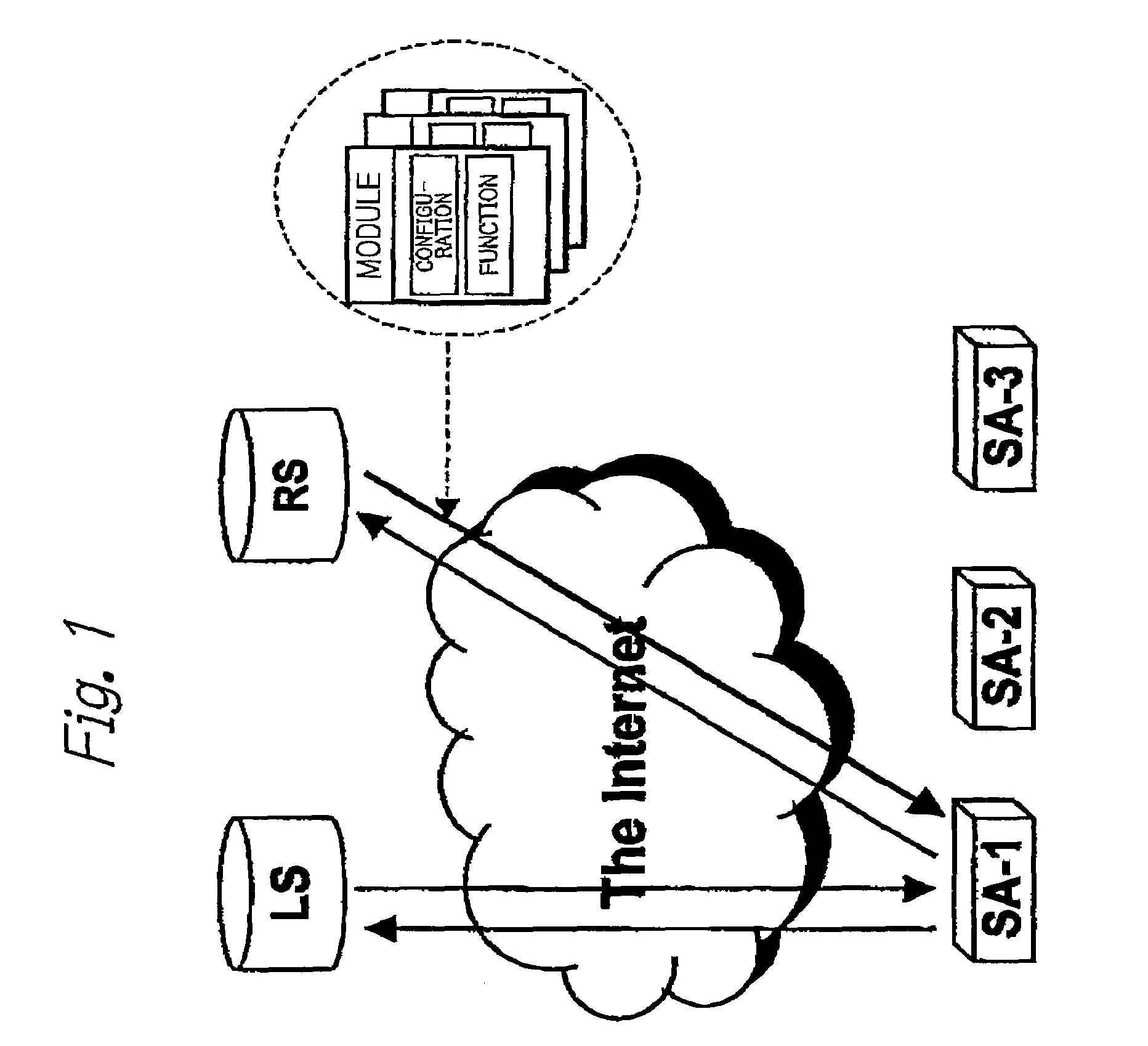
[0036]FIG. 1 shows an outline of a configuration of a system of the version 2 according to the present invention. A location server (LS) for providing connection data to a resource server responsible for each service adapter and a resource server (RS) for providing configuration and function for the service adapter are shown. In the system according to the present invention, only one location server is present. On the contrary, a plurality of resource servers may be present.

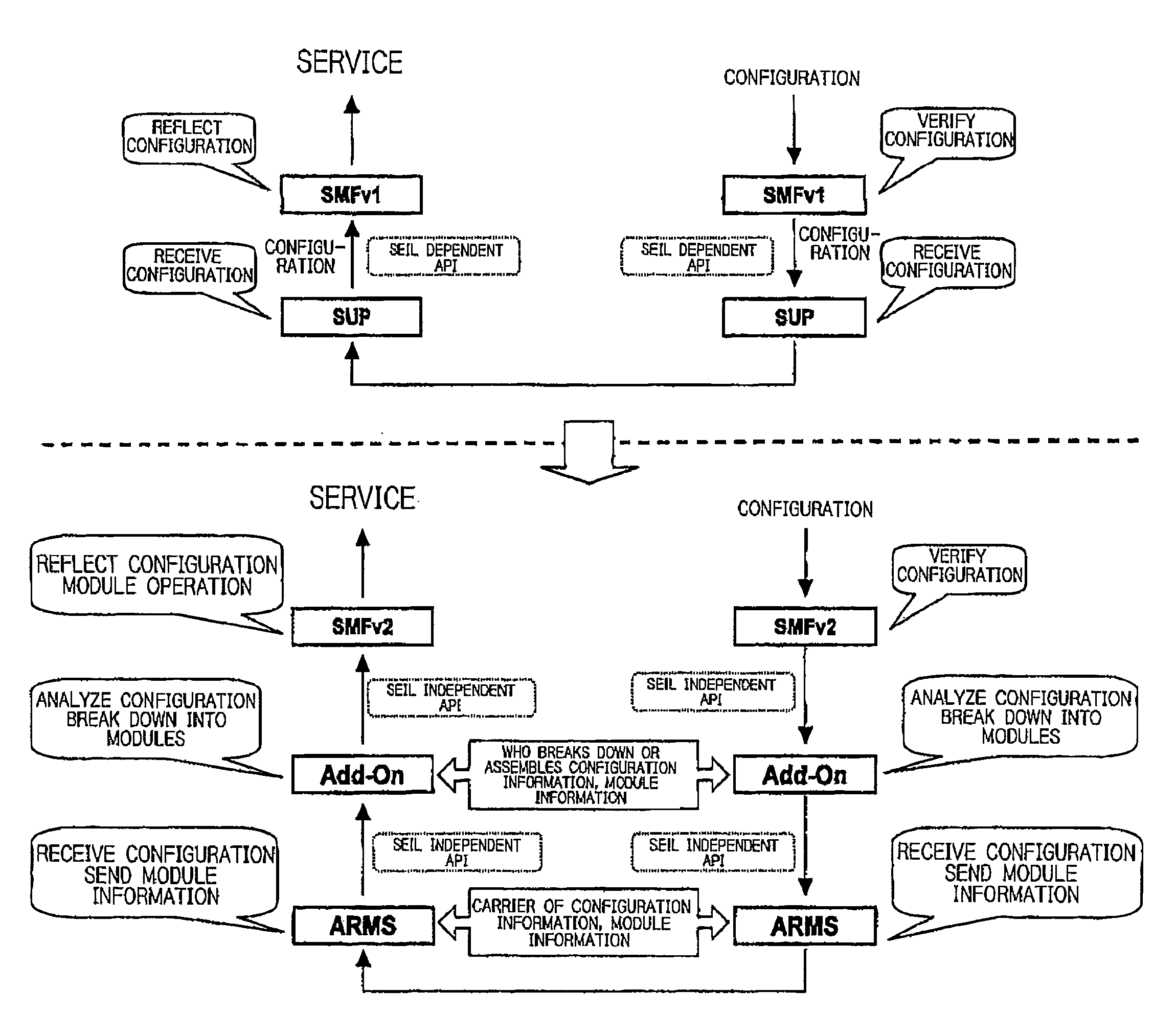
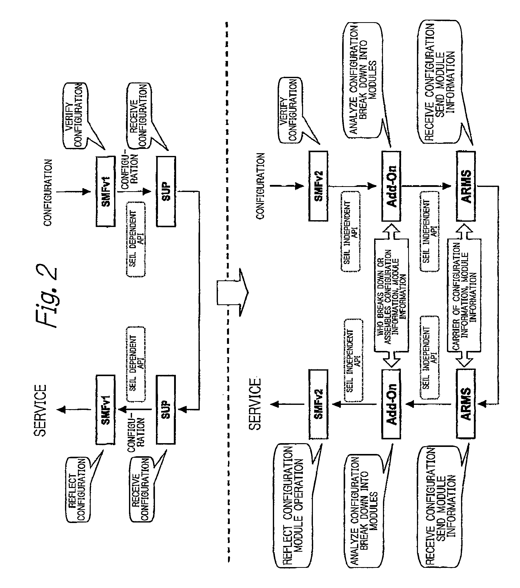
[0037]FIG. 2 shows a layer structure in the version 1 (above the dotted line) and a layer structure in the version 2 (below the dotted line). In the system of the version 2 according to the present invention, an Add-...


PUM


Abstract

To provide a system enabling a function for implementing providing of a service desired by an end user to be automatically generated in a network connecting appliance.When a resource server (RS) receives a request for a specification which is desired to be implemented from a particular service adapter (SA), the requested specification is analyzed by a specification analyzing device, a virtual service adapter is formed by collecting functional modules required to implement the specification, and the formed virtual service adapter is provided for the requesting service adapter. The virtual service adapter is automatically set as a physical service adapter to implement an actually requested function in a service adapter at an end user's place.

Description

BACKGROUND OF THE INVENTION[0001]1. Field of the Invention[0002]The present invention relates to a management and operation system for appliances connected to a network. More specifically, the present invention relates to a management and operation system which enables various functions which were not originally included in the appliances to be automatically generated from a distance according to a user's desire to use various appliances connected to a communication network.[0003]2. Description of the Related Art[0004]The present invention is the system and method proposed in Japanese Patent Application No. 2002-359720 titled “Central management system and method of network connecting means” filed on Dec. 11, 2002, (hereinafter simply called “a previous application”) by an applicant of this patent application with improvement and new features added. Thus, the invention of the previous application will be outlined before describing the present invention.[0005]A widely used router of ...

Claims


Application Information

Patent Timeline
Patent Type & Authority Patents(United States)
IPC IPC(8): H04L12/28G06F15/173G06F15/177
CPCH04L12/66H04L41/082H04L41/0886H04L41/0895
Inventor ISHIDA, KIYOSHIHAYASHI, KENICHIROOKI, MASARUEBISAWA, SATOSHISUENAGA, HIROKI
Owner INTERNET INITIATIVE JAPAN
Learn More