
System and method for simulating network connection characteristics

Inactive Publication Date: 2005-04-28
MICROSOFT TECH LICENSING LLC
View PDF15 Cites 13 Cited by
  • Summary
  • Abstract
  • Description
  • Claims
  • Application Information

AI Technical Summary

Benefits of technology

[0009] To overcome the limitations in the prior art as described above and other limitations that will become apparent upon reading and understanding the present specification, the present invention is a system and method for simulating network connection characteristics by alteration of network packets. The present invention provides simulation of major network connection characteristics and realistically simulates the effects that network devices (such as routers and communication links) impose on network packets. These effects include, for example, transmission delay, limited bandwidth, packet dropping, packet fragmentation, packet duplication and packet reordering. The present invention provides a wide range of realistic simulated effects on network connection characteristics that are useful in the testing and capacity planning of a network server.

Problems solved by technology

However, this approach is both expensive and time-intensive.
One problem with this approach, however, is that characteristics of a LAN and of a WAN are usually very different.
Thus, testing a WAN server on a LAN usually does not yield accurate results.
Conversely, on a WAN, a packet usually travels large distances and takes much longer to reach its destination.
In addition, a WAN usually includes network devices (such as communication links and routers) that impose delays that further slow the propagation of packets over the network.
This packet fragmentation also imposes an extra burden on the server.
One problem, however, with hardware simulators is that they are expensive and do not provide simulation of all the above-mentioned network connection characteristics.
This reduces the accuracy of the simulation because a LAN only sends packets from a limited number of sources.

Method used


Image

  • System and method for simulating network connection characteristics
  • System and method for simulating network connection characteristics
  • System and method for simulating network connection characteristics

Examples


Embodiment Construction

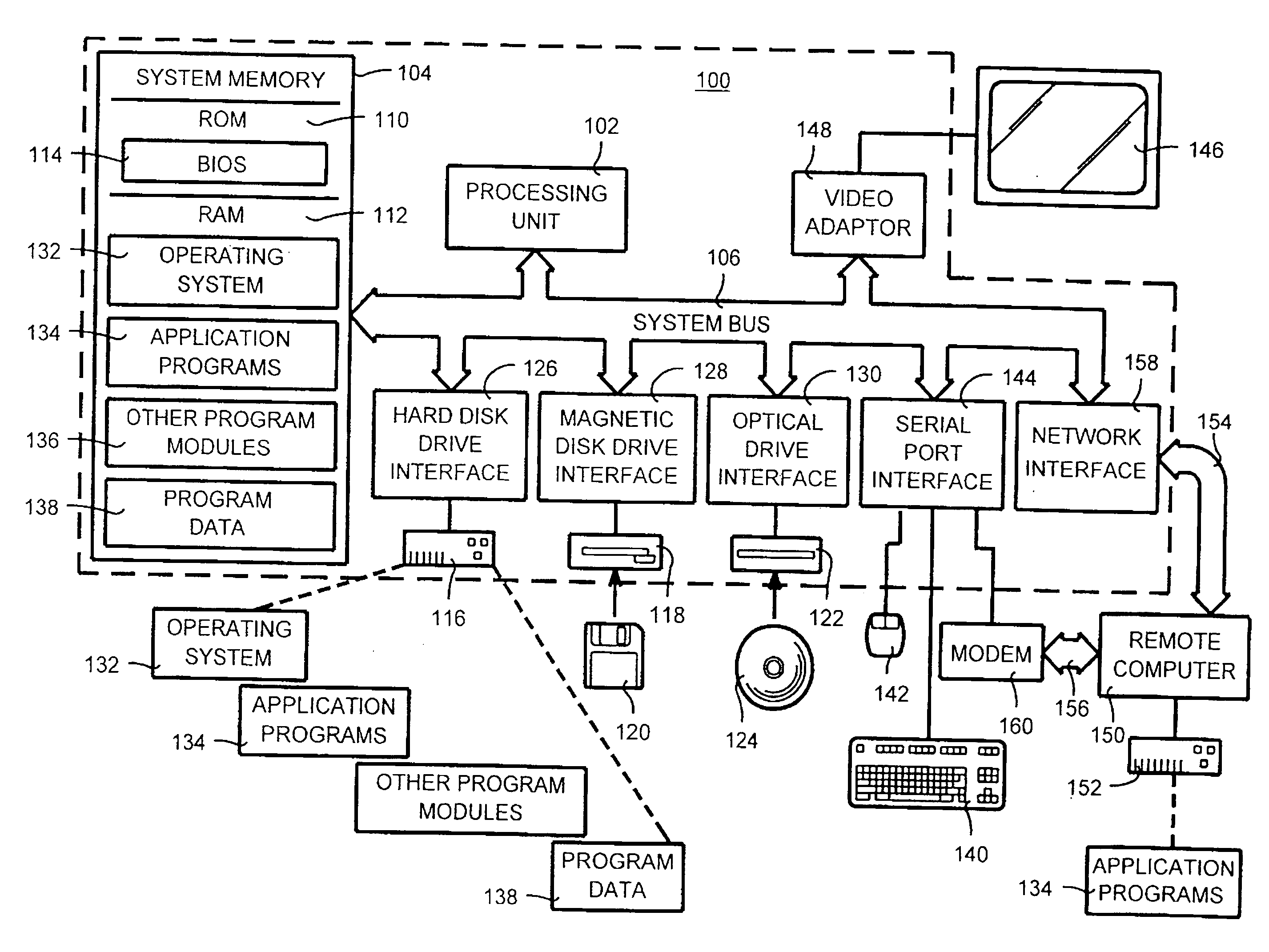
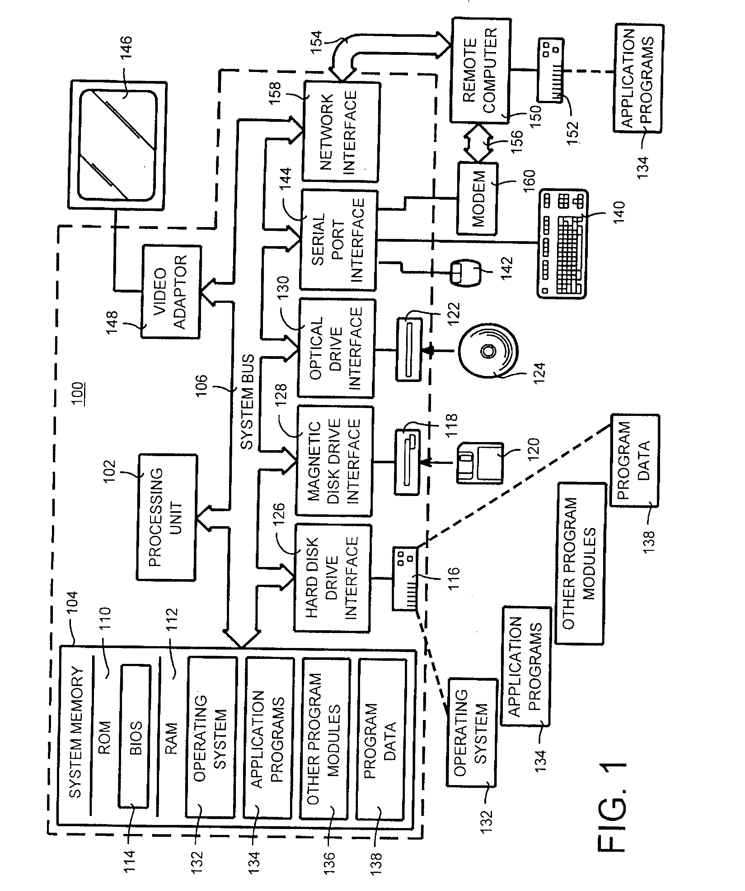
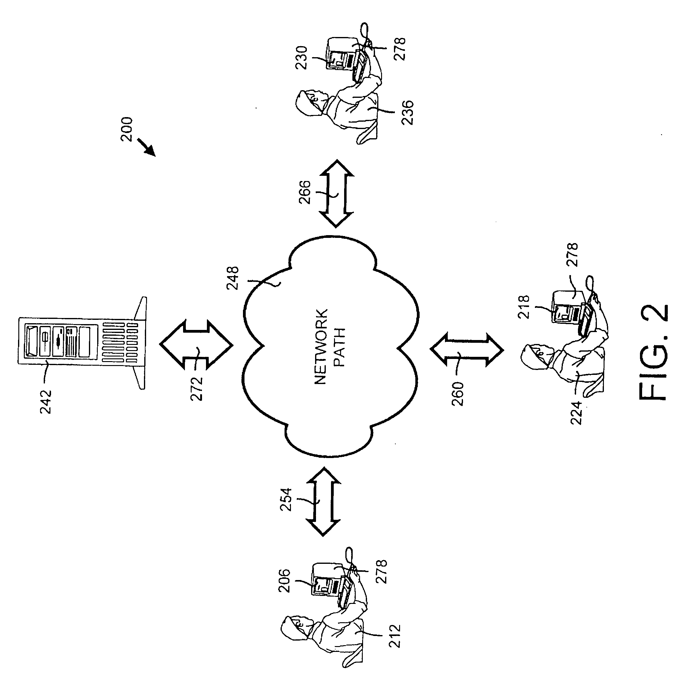
[0026] In the following description of the invention, reference is made to the accompanying drawings, which form a part thereof, and in which is shown by way of illustration a specific example whereby the invention may be practiced. It is to be understood that other embodiments may be utilized and structural changes may be made without departing from the scope of the present invention.

I. Introduction

[0027] The present invention is embodied in a system and method for simulating network connection characteristics. These connection characteristics are simulated by altering, for example, the timing, placement and structure of network packets. Network connection characteristics that may be simulated by the present invention include packet transmission delay, bandwidth constriction, packet loss, packet fragmentation, packet duplication and packet reordering. In addition, the present invention includes a network address translation feature for simulating multiple clients accessing a tar...


PUM


Abstract

A system and method for simulating network connection characteristics by alteration of a network packet. In general, the method of the invention includes providing a driver that is capable of accessing all outgoing and incoming network packets and altering a network packet to simulate a connection characteristic of the network. In particular, the method of the invention includes receiving a network packet, assigning a new, simulated network address to the network packet and performing modification of the network packet to simulate certain network connection characteristics (including, for example, transmission delay, limited bandwidth, packet dropping, packet fragmentation, packet duplication and packet reordering). The system of the invention includes a modification module for altering certain characteristics of a packet. The modification module is capable of mapping a new, simulated network address to a network packet, modifying a propagation characteristic of the network connection, and altering an additional packet characteristic.

Description

CROSS REFERENCE TO RELATED APPLICATIONS [0001] This application is a continuation of U.S. patent application Ser. No. 09 / 460,688, entitled “System and Method for Simulating Network Connection Characteristics,” filed Dec. 14, 1999, the entire contents of which are hereby incorporated by reference.TECHNICAL FIELD [0002] The present invention relates in general to computer network simulation and more particularly to a system and a method for simulating network connection characteristics by alteration of network packets. BACKGROUND OF THE INVENTION [0003] Capacity planning of a server used in a server / client wide-area network (WAN) is quickly becoming more important as the use of WANs (such as the Internet) rapidly increase. WAN servers often are used by Internet sites and must be able to efficiently handle the anticipated requests to the site. Capacity planning helps predict if and when system saturation will occur by testing the maximum user load and speed of the target server. Thus, ...

Claims


Application Information

Patent Timeline
IPC IPC(8): H04L12/24
CPCH04L43/50H04L41/145
Inventor PATIEJUNAS, KESTUTIS
Owner MICROSOFT TECH LICENSING LLC
Learn More