Exhaust gas temperature sensor inspecting apparatus

a technology for temperature sensors and exhaust gas, which is applied in the direction of heat measurement, electric control, instruments, etc., can solve the problems of sensor failure and decreased sensor ability of catalyst of catalytic converter installed in the exhaust system of a vehicle, and achieve the effect of accurate determination

Inactive Publication Date: 2010-03-02
HONDA MOTOR CO LTD
View PDF10 Cites 2 Cited by
  • Summary
  • Abstract
  • Description
  • Claims
  • Application Information

AI Technical Summary

Benefits of technology

[0013]According to this aspect, failure of the temperature sensor may be accurately determined. Accurate determination of the failure is required for maintenance of the particulate filter of the diesel engine.

Problems solved by technology

The ability of a catalyst of a catalytic converter installed in an exhaust system of a vehicle may decrease if the catalytic converter is exposed to an abnormally high temperature.
If an inspection for a temperature sensor is performed under a condition that a temperature of an exhaust system is low, for example, immediately after the engine starts, the sensor may produce a fixed output value due to the low temperature even if the temperature sensor is normal, which may lead to a wrong detection that the sensor is in a failure.

Method used


Image

  • Exhaust gas temperature sensor inspecting apparatus
  • Exhaust gas temperature sensor inspecting apparatus
  • Exhaust gas temperature sensor inspecting apparatus

Examples


Embodiment Construction

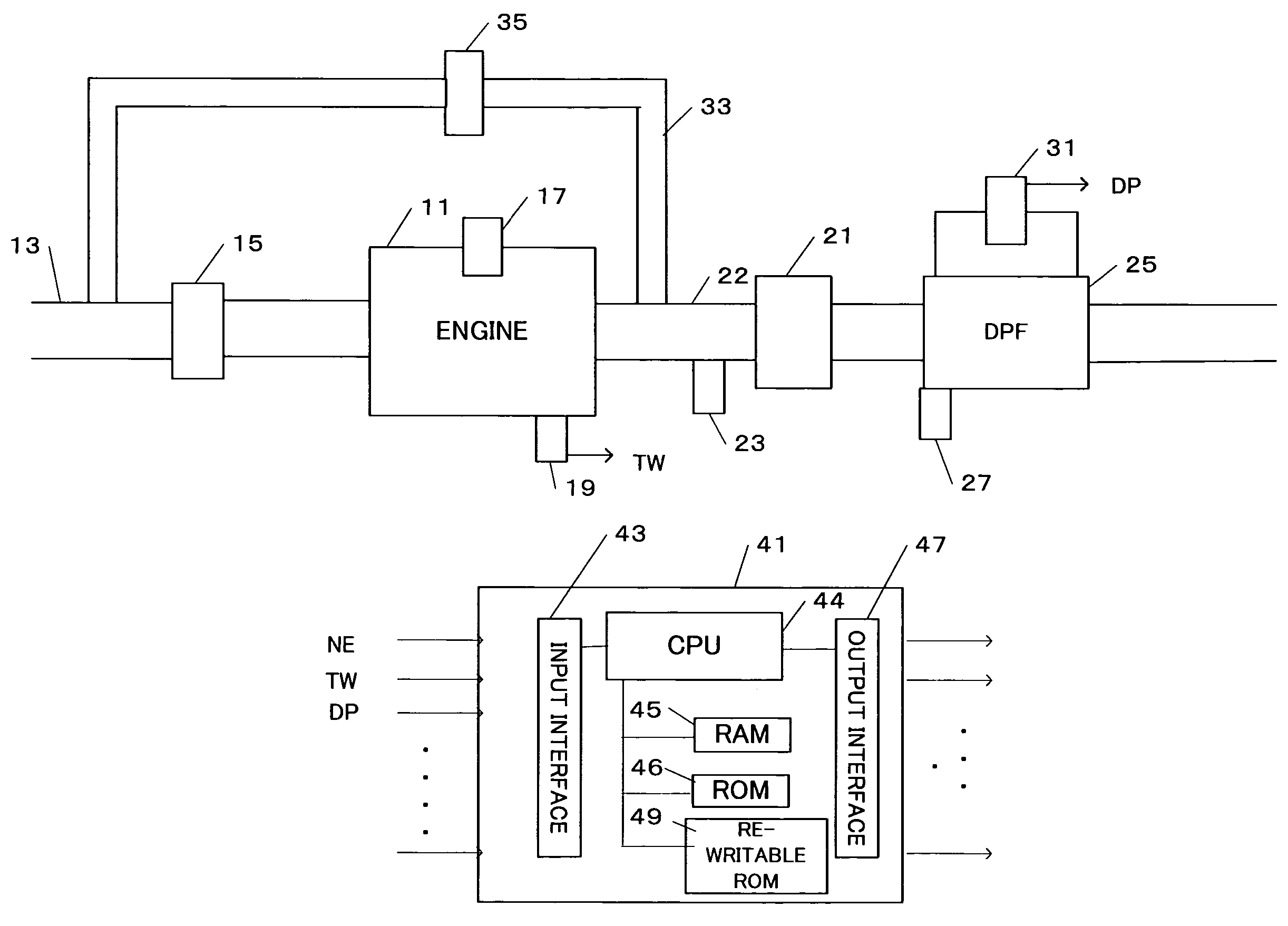
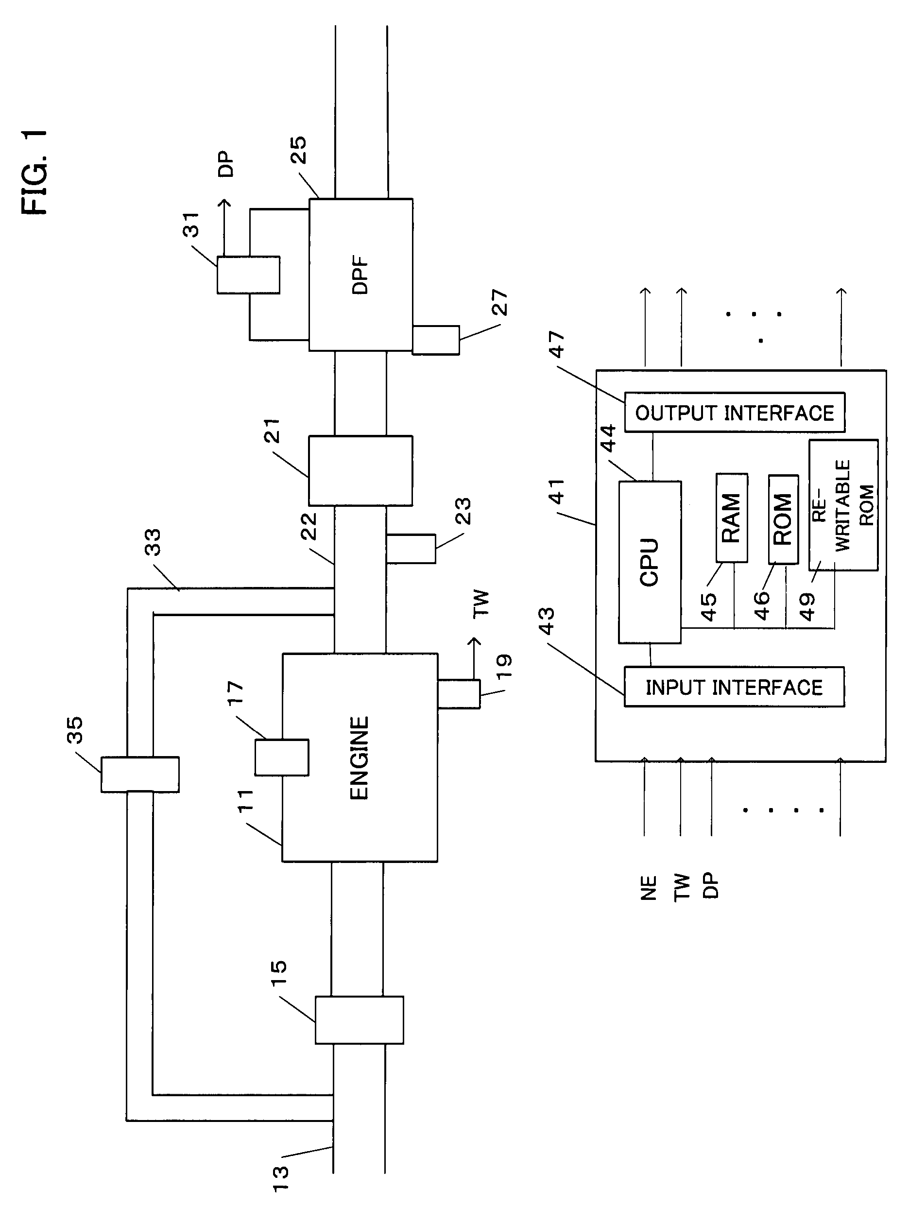
[0019]Preferred embodiments of the present invention will be described below with reference to the accompanying drawings. FIG. 1 is a block diagram showing an overall structure of a system in which the present invention is applied to an exhaust system of a diesel engine. A fuel injecting device, that is, an injector 17, is provided in each cylinder of a diesel engine 11 and a water temperature sensor 19 for detecting a temperature TW of cooling water is disposed in a cylinder block. An exhaust gas recirculation (EGR) passage 33 is provided from an exhaust pipe 22 to an air intake pipe 13. An amount of EGR is controlled by an EGR controlling valve 35.

[0020]An oxidizing catalyst 21 and a diesel particulate filter (DPF) 25 are disposed in the exhaust pipe 22. The oxidizing catalyst 21 typically comprises a honeycomb-shaped medium of cordierite or heat resisting steel, whose surface is coated with activated alumina or the like. This coating layer contains catalyst-activating elements of...


PUM

PropertyMeasurementUnit
temperatureaaaaaaaaaa

Abstract

A temperature sensor disposed in an exhaust system of an engine is inspected. Determination is made that conditions for inspecting the temperature sensor are satisfied in the current engine load range. The time for the temperature in the exhaust system to reach a value appropriate for checking the temperature sensor is determined in accordance with engine water temperature. Output of the temperature sensor is checked to determine if the temperature sensor is normal at the determined time.

Description

BACKGROUND OF THE INVENTION[0001]The present invention relates to an apparatus for inspecting a temperature sensor disposed in an exhaust system of an internal combustion engine.[0002]The ability of a catalyst of a catalytic converter installed in an exhaust system of a vehicle may decrease if the catalytic converter is exposed to an abnormally high temperature. In order to control the temperature of the catalyst, a temperature sensor is usually disposed in the vicinity of the catalyst. This temperature sensor generally uses a thermistor having lower resistance at higher temperature. The value of resistance becomes larger as the temperature becomes lower.[0003]The Japanese Patent Application Publication No. S59-120835 discloses a technique for detecting breaking of a temperature sensor by providing a second reference power supply for generating a second voltage signal different from a voltage signal from the temperature sensor at a normal time. The second voltage signal is compared ...

Claims


Application Information

Patent Timeline
Patent Type & Authority Patents(United States)
IPC IPC(8): G01N3/60
CPCF01N11/002F02D41/1446F02D41/222F01N2560/06Y02T10/40Y02T10/47
Inventor OKAYASU, KOUJIISHIHARA, YOSHINORI
Owner HONDA MOTOR CO LTD
Why Eureka
Try Eureka