
Hall-effect pressure switch

a technology of pressure switch and hall effect, which is applied in the direction of pulse technique, magnetic body, instruments, etc., can solve the problems of preventing the circuit from working properly and limiting the application of the circuit further

Inactive Publication Date: 2010-03-16
GM GLOBAL TECH OPERATIONS LLC
View PDF14 Cites 5 Cited by
  • Summary
  • Abstract
  • Description
  • Claims
  • Application Information

AI Technical Summary

Problems solved by technology

Although metal contacts are an acceptable means of conducting current flow, the contacts can form insulating oxides that corrode the metal and prevent the circuit from working properly.
However, further applications are limited.

Method used


Image

  • Hall-effect pressure switch
  • Hall-effect pressure switch
  • Hall-effect pressure switch

Examples


Embodiment Construction

[0016]The following description of the preferred embodiment is merely exemplary in nature and is in no way intended to limit the invention, its application, or uses. For purposes of clarity, the same reference numbers will be used in the drawings to identify similar elements.

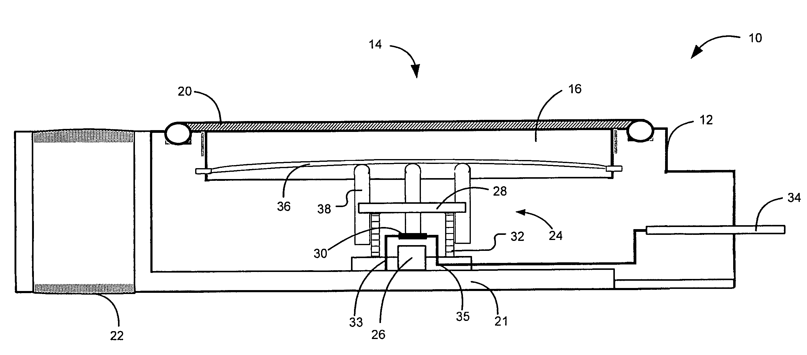
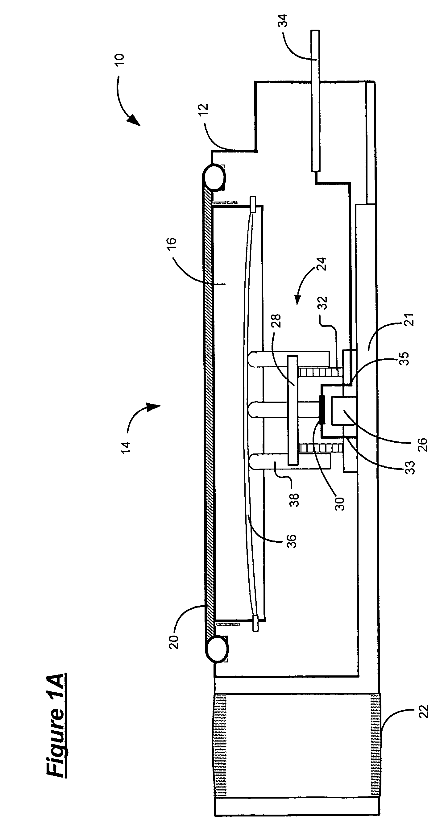
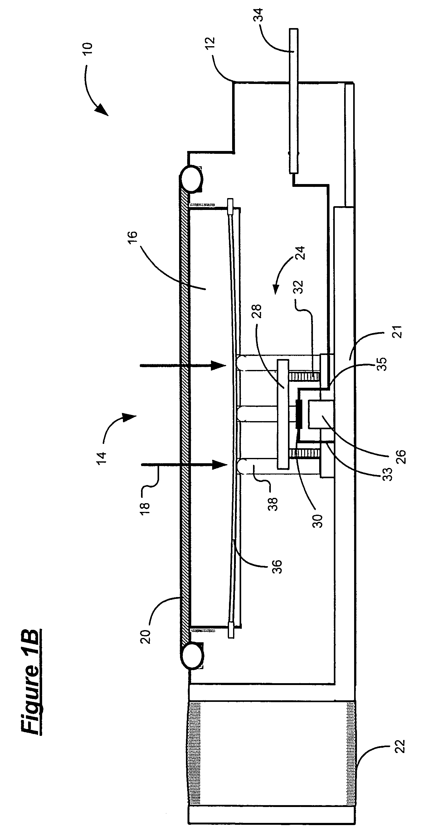
[0017]Referring now to FIGS. 1A and 1B, an exemplary hall-effect switch 10 adapted to detect fluid pressure is shown. The hall-effect switch 10 includes an outer housing 12 having a top 14 and a pressure chamber 16 within the housing that holds fluid 18. The top couples to a fluid pressure source (not shown) and functions as an inlet to direct fluid 18 to the pressure chamber 16. A sealing device 20 is attached to the housing 12 and surrounds the top 14 to prevent fluid 18 from escaping the switch 10. A metal plate 21 is disposed on the inner base of the housing. A mounting fixture 22 can be coupled to one side of the switch where it couples to the metal plate 21. When the mounting fixture 22 contacts a ground s...


PUM


Abstract

A switch includes housing and a magnet that is mounted inside the housing. The magnet generates a magnetic field having magnetic flux. The switch further includes a flux concentration device that is located inside the housing and that selectively moves between first and second positions. An actuator assembly is located inside the housing and selects the first and second positions based on the input. A hall-effect device is located between the magnet and the flux concentration device and conducts a current having a first value when the magnetic flux is less than a predetermined magnetic flux threshold. The hall-effect device conducts current having a second current value when the magnetic flux exceeds the predetermined magnetic flux threshold. The first position communicates a first magnetic flux to the hall-effect device and the second position communicates a second magnetic flux that is different from the first magnetic flux to the hall-effect device.

Description

FIELD OF THE INVENTION[0001]The present invention relates to vehicle diagnostic systems, and more particularly to a switch system for detecting faults in an electrical circuit.BACKGROUND OF THE INVENTION[0002]Single throw switches can be used in vehicles to detect the presence of an input, such as fluid pressure. A simple switch includes two metal contacts that selectively connect to conduct current and complete a circuit. Although metal contacts are an acceptable means of conducting current flow, the contacts can form insulating oxides that corrode the metal and prevent the circuit from working properly.[0003]Single throw switches operate in two modes, or positions. A first position separates the two contacts to provide an open circuit. A second position connects the contacts to complete the circuit (i.e. close the circuit) and to provide a current path. Accordingly, single throw switches are convenient for switching power to a circuit. However, further applications are limited.SUM...

Claims


Application Information

Patent Timeline
Patent Type & Authority Patents(United States)
IPC IPC(8): G01R33/06H01L43/06
CPCH03K17/9505H03K17/9517H03K17/97H01H35/34
Inventor KOSKI, JACK P.
Owner GM GLOBAL TECH OPERATIONS LLC
Learn More