Diverter assembly, printing system and method

a printing system and diverter technology, applied in the field of printing systems, can solve problems such as unsatisfactory occurrences, such as vibration and/or noise levels, and may become elevated, creating a jam or other undesirable condition,

Inactive Publication Date: 2010-03-23
XEROX CORP
View PDF88 Cites 5 Cited by
  • Summary
  • Abstract
  • Description
  • Claims
  • Application Information

AI Technical Summary

Problems solved by technology

One difficulty with such known arrangements, however, is associated with the continued demand for and corresponding advancement of the performance of printing systems (e.g., increased output in pages per minute).
Thus, undesirable occurrences, such as impacts, vibrations and / or noise levels, for example, may become elevated due, at least in part, to these more frequent gate switching operations.
Another difficulty with known gate arrangements, which is also associated with the advancing performance of printing systems, involves the timing between the passing of a first sheet of media, the movement of the gate to a different position, and the arrival of a second sheet of media.
It is well known that the arrival of a second sheet of media at a diversion point prior to a gate reaching a desired gate position could result in the leading edge of the sheet of material contacting the upstream edge of the gate and thereby creating a jam or other undesirable condition.
However, while such techniques seem to work well at known printing system performance levels, as sheet media speeds increase and IDGs are reduced, the window for initiating the gate switch is reduced, Furthermore, care is normally exercised to ensure that that the upstream edge of the gate does not pinch or otherwise engage the first sheet of media, such as along the trailing edge thereof, and thereby undesirably slow or disrupt the movement of the sheet, This may be of particular concern where an advancement in the timing of the gate switching operations is being used to increase performance of the printing system.

Method used


Image

  • Diverter assembly, printing system and method
  • Diverter assembly, printing system and method
  • Diverter assembly, printing system and method

Examples


Embodiment Construction

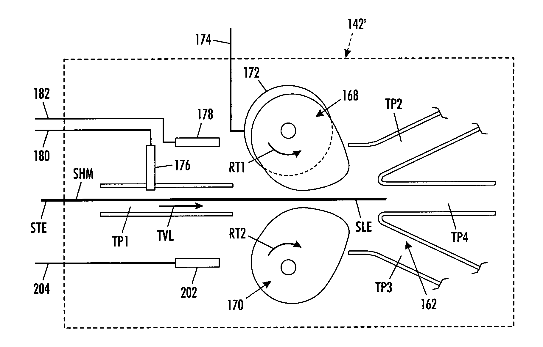
[0064]The subject matter of the present disclosure is capable of broad use in a wide variety of applications and environments, including use in association with printing systems of any suitable type, kind and / or configuration. For example, the subject matter of the present disclosure can be used on printing systems embodied as desktop printers, stand-alone copiers, multi-function (e.g., print / copy / fax) machines, and / or production-oriented or high-speed publishing equipment. Additionally, such printing systems can utilize any suitable type or kind of marking process or substance, such as a xerographic process using toner or an inkjet process using liquid ink, for example. Furthermore, it will be appreciated that the subject matter of the present disclosure is particularly well suited for use in association with printing systems having high output capacity, such as production printing and publishing systems, for example. However, any reference herein to such specific application and / o...


PUM

PropertyMeasurementUnit
phase angleaaaaaaaaaa
rotational phase angleaaaaaaaaaa
rotational phaseaaaaaaaaaa

Abstract

A diverter assembly includes at least one rotary member disposed along a media transport pathway adjacent a diversion point therealong. The diverter assembly also includes a rotational motion source in operative association with the at least one rotary member. A printing system includes a diverter assembly. A method of transporting sheet media includes utilizing a diverter assembly.

Description

BACKGROUND[0001]The present disclosure broadly relates to the art of printing systems and, more particularly, to at least a diverter assembly, a printing system including a diverter assembly, and a method of transporting sheet media.[0002]Known printing systems commonly include two or more media transport paths that divert from one another at certain points and join one another at other points. Thus, a given sheet of media can normally be transported through a known printing system along any one of a variety of transport paths.[0003]One example of printing systems in which such various transport paths are utilized are those printing systems having multiple marking engines. In such printing systems, sheets of media are selectively transported from a media supply to one of two or more marking engines. Thus, a diversion point is provided along the transport pathway at which one or more sheets of media will be directed toward one of the two or more marking engines.[0004]Upon reaching th...

Claims


Application Information

Patent Timeline
Patent Type & Authority Patents(United States)
IPC IPC(8): B65H39/10
CPCB65H29/58B65H2301/44822B65H2404/1414B65H2404/1415B65H2404/631
Inventor DEGRUCHY, PAUL J.
Owner XEROX CORP
Why Eureka
Try Eureka