Electrical connector with metallic shell

a technology of electric connectors and metallic shells, applied in the direction of coupling device connections, connection contact material, coupling protective earth/shielding arrangements, etc., can solve the problems of difficult effective suppression of electromagnetic emissions, and achieve the effect of suppressing electro magnetic interference and improving shielding structur

Inactive Publication Date: 2010-03-23
HON HAI PRECISION IND CO LTD
View PDF5 Cites 3 Cited by
  • Summary
  • Abstract
  • Description
  • Claims
  • Application Information

AI Technical Summary

Benefits of technology

[0006]Accordingly, an object of the present invention is to provide an electrical connector assembly with an improved shielding structure to suppress electro magnetic interference.

Problems solved by technology

Thus, the effective suppression of electromagnetic emissions remains a challenge.

Method used


Image

  • Electrical connector with metallic shell
  • Electrical connector with metallic shell
  • Electrical connector with metallic shell

Examples


Embodiment Construction

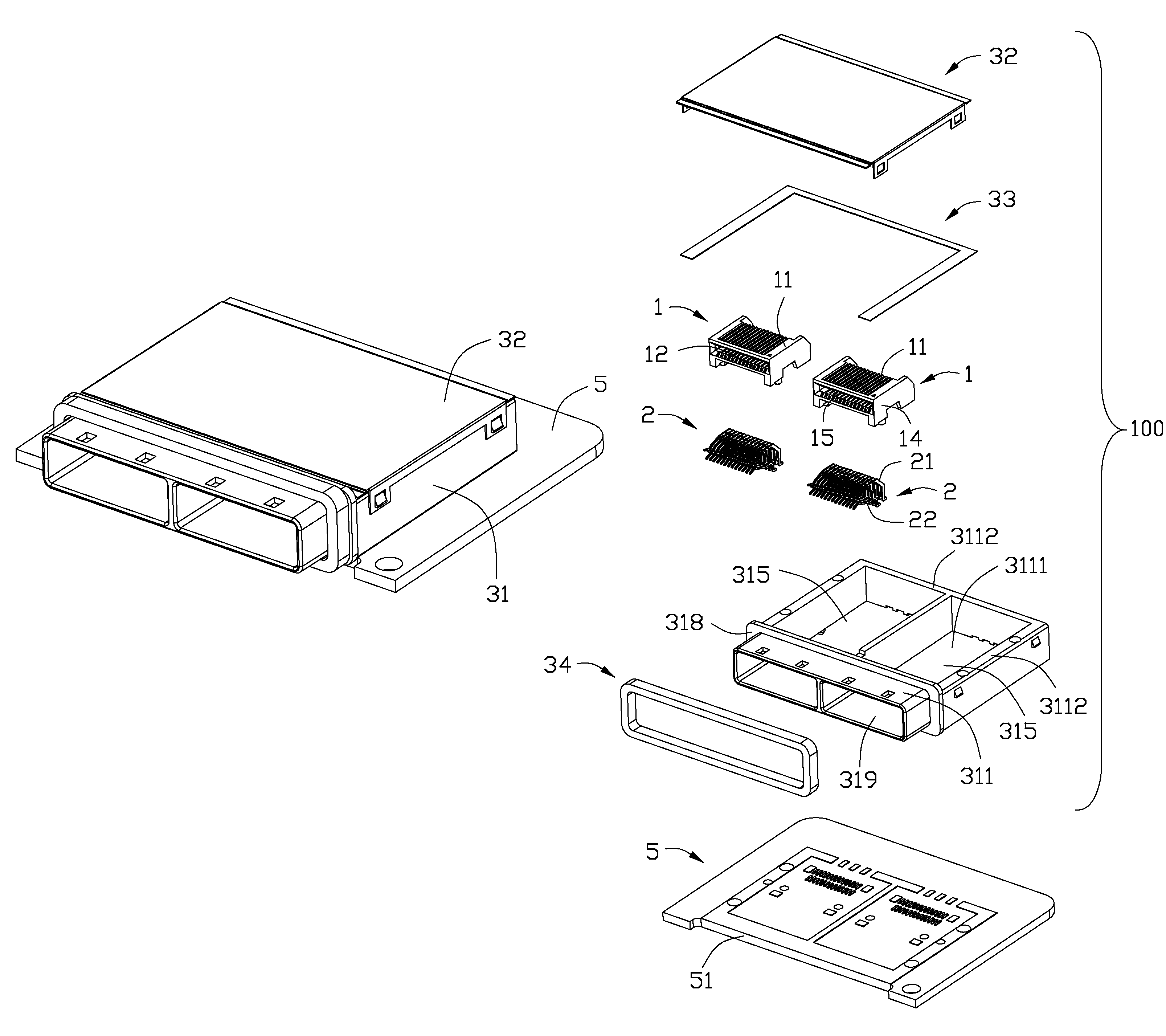
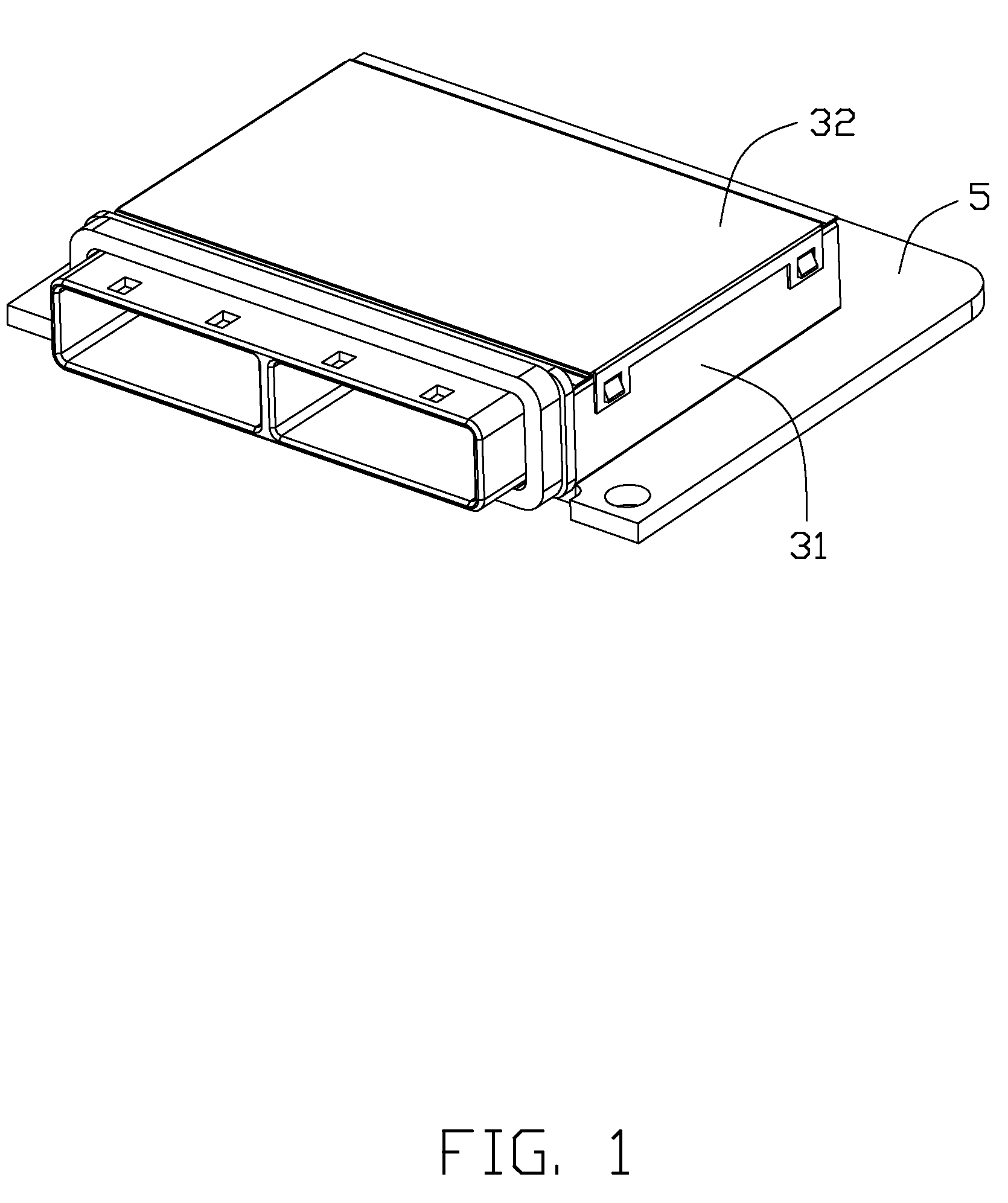
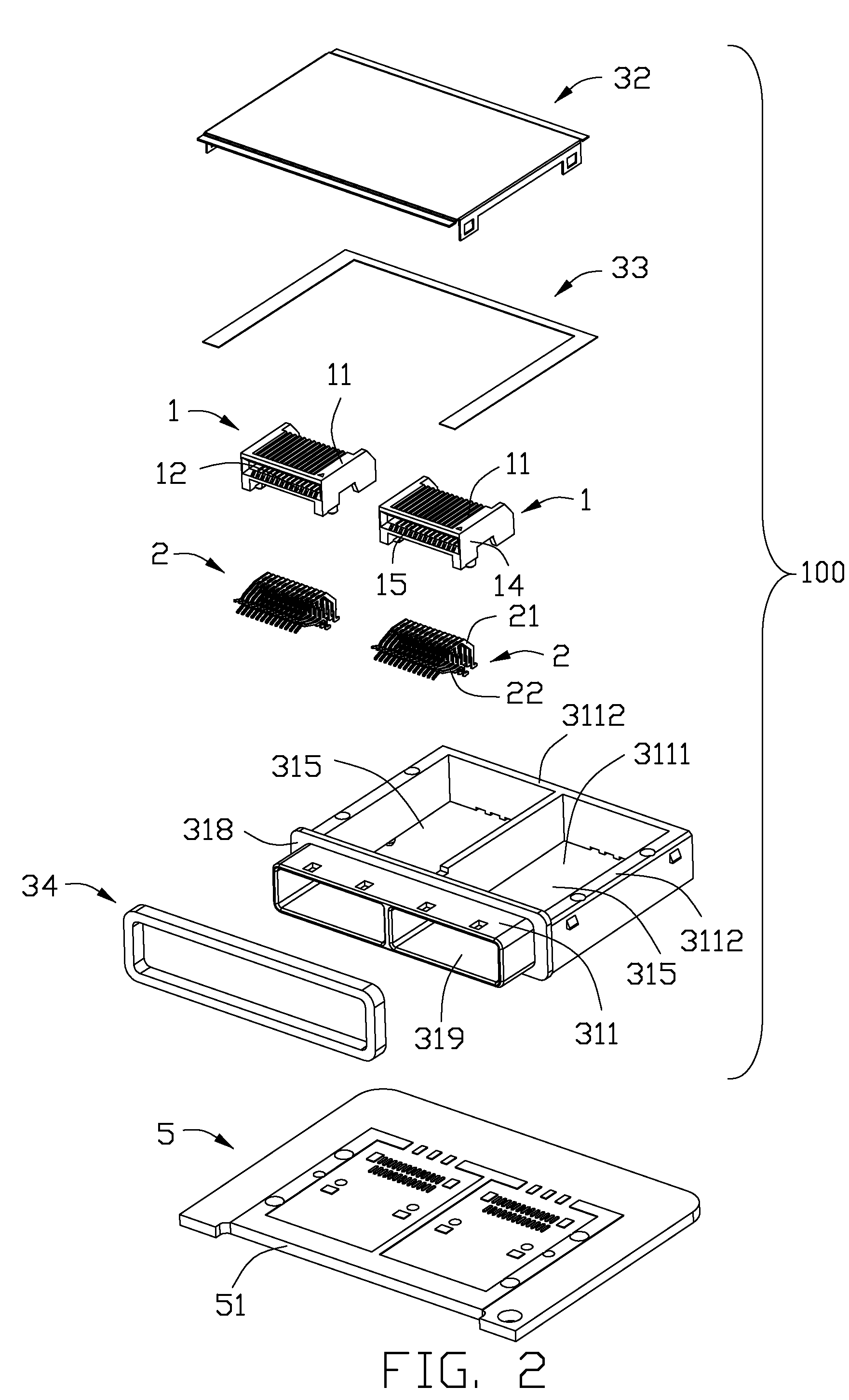
[0012]Referring to FIG. 1 to 2, an electrical connector 100 for providing a connection between a printed circuit board 5 and a complementary connector (not shown, according to an embodiment of the present invention is shown to comprise an insulative housing 1 defining a lengthwise slot 15, a plurality of terminals 2 received in the insulative housing 1 and extending into the lengthwise slot 15, a metal shell 3.

[0013]The insulative housing 1 comprises an upper wall 11, a lower wall 12, a rear wall and a pair of side wall 14. The upper wall 11, the lower wall 12, the pair of side wall 14 and the rear wall cooperatively defining a lengthwise slot 15. The terminals 2 which are assembled to the insulative housing 1 are arranged into a first group of terminals 21 and a second group of terminals 22, the first group of terminals 21 are assembled to the insulated housing 1 along a front-to-back direction and the second group of terminals 22 are assembled to the insulated housing 1 along a ve...


PUM


Abstract

An electrical connector comprises an insulative housing defining a lengthwise slot, a plurality of terminals received in the insulative housing and extending into the lengthwise slot, a metal shell, and an EMI gasket. The metal shell comprises a body portion with a front insertion port and a detachable metal cover, the body portion defines a hollow to receive the insulative housing. The body portion comprises a top wall defining a through window and a bottom wall defining a through opening, the metal cover covers the window of the body portion, and the EMI gasket is located between the body portion and the metal board portion for suppressing electro magnetic interference.

Description

BACKGROUND OF THE INVENTION[0001]1. Field of the Invention[0002]The present invention relates to an electrical connection device, and more particularly to an electrical connector with a metallic shell shielding a pair of connector therein.[0003]2. Description of Related Art[0004]CN Pat. No. 201038454 issued to TIAN-QING CAI on Mar. 19, 2008, discloses an electrical connector comprising an insulative housing defining a lengthwise slot, a plurality of terminals received in the insulative housing and extending into the lengthwise slot, and a metallic shell. The metallic shell comprises a body portion with a front opening for insertion of a mating connector, the body portion defining a hollow space to receive the insulative housing and a detachable metallic cover. The body portion comprises a top wall defining a window and a bottom wall defining a opening, the detachable metallic cover shields the window of the body portion. There is between the body portion and the cover a space, throu...

Claims


Application Information

Patent Timeline
Patent Type & Authority Patents(United States)
IPC IPC(8): H01R13/648
CPCH01R13/648
Inventor YUAN, WEIHSIAO, YU-SAN
Owner HON HAI PRECISION IND CO LTD
Why Eureka
Try Eureka