Touch panel

A touch panel and substrate technology, which is applied in the input/output process of instruments, electrical digital data processing, and data processing, etc., can solve problems such as the reduction of the distance between the shielding structure and the signal line, and the electrostatic damage to the signal line.

Inactive Publication Date: 2016-08-03
INNOLUX CORP
View PDF6 Cites 9 Cited by
  • Summary
  • Abstract
  • Description
  • Claims
  • Application Information

AI Technical Summary

Problems solved by technology

However, as the frame of the touch panel narrows, the distance between the shielding structure and the signal lines decreases. Wh...

Method used


Image

  • Touch panel
  • Touch panel
  • Touch panel

Examples


Embodiment Construction

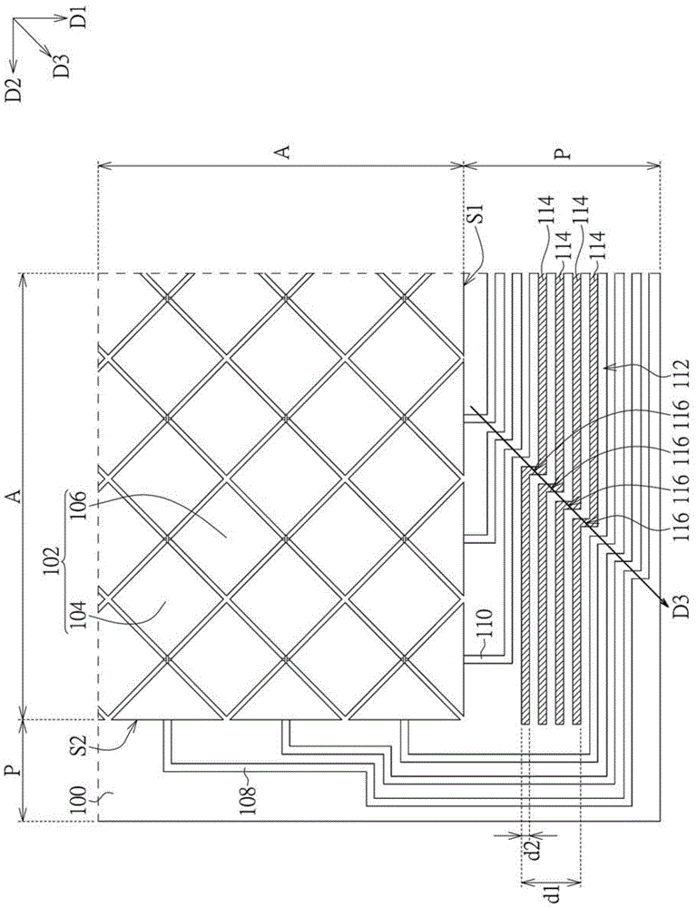
[0027] Please refer to figure 1 , which shows a partial structure of the touch panel according to an embodiment of the present invention. The touch panel includes a substrate 100 , a sensing pattern 102 , a plurality of first signal lines 108 , a plurality of second signal lines 110 and a shielding structure 112 .

[0028] The substrate 100 has a first direction D1 and a second direction D2. The first direction D1 and the second direction D2 are perpendicular to each other. The substrate 100 includes an active area A and a peripheral area P. The active region A has a first edge S1 and a second edge S2 connected to each other, extending along the second direction D2 and the first direction D1 respectively. The peripheral area P is located outside the active area A. As shown in FIG.

[0029] The sensing pattern 102 is disposed on the active area A of the substrate 100 . The sensing pattern 102 includes a plurality of first sensing electrodes 104 and a plurality of second se...


PUM

PropertyMeasurementUnit
Widthaaaaaaaaaa

Abstract

The invention discloses a touch panel, which comprises a substrate, a sensing pattern, first signal cables, second data cables and a shielding structure, wherein the substrate has a first direction and a second direction, and the first direction is perpendicular to the second direction; the substrate comprises an active area and a peripheral area, and the peripheral area is positioned on the outer side of the active area; the sensing pattern is arranged on the active area of the substrate; the first signal cables are arranged on the peripheral area of the substrate, and are coupled to the sensing pattern in the first direction; the second signal cables are arranged on the peripheral area of the substrate, and are coupled to the sensing pattern in the second direction; the shielding structure is arranged on the peripheral area of the substrate, is positioned between the first and second signal cables, and comprises shielded wires with step-like turning areas; a third direction forms an included angle with the second direction, and the step-like turning areas are arranged in the third direction.

Description

technical field [0001] The present invention relates to a touch panel, in particular to a touch panel including a shielding structure. Background technique [0002] The touch panel provides a simple and intuitive input method. By converting the user's touch into an electrical signal, the touch panel can be operated by the user by selecting, sliding, and the like. Common touch panels include resistive and capacitive touch panels, which operate by detecting changes in resistance and capacitance caused by touch, respectively. These changes are further transmitted to the processor via signal lines. Shielding structures may be provided between signal lines coupled to different sensing electrodes to isolate signals from different sensing electrodes. Typically, such a shielding structure can be provided as an entire strip of conductive material. However, as the frame of the touch panel narrows, the distance between the shielding structure and the signal lines decreases. When th...

Claims


Application Information

Patent Timeline
IPC IPC(8): G06F3/041
Inventor 简传枝朱逸洁
Owner INNOLUX CORP
Why Eureka
Try Eureka